NAVIGATION / MULTI INFO DISPLAY NAVIGATION SYSTEM(for Radio and Display Type with Single Knob Type) B15C371 Speaker Output Short Actuator Stuck
DESCRIPTION
This DTC is stored when the radio and display receiver assembly*1 or stereo component amplifier assembly*2 detects a short in a speaker circuit.
*1: for 6 Speakers
*2: for 9 Speakers
| DTC No. | Detection Item | DTC Detection Condition | Trouble Area |
|---|---|---|---|
| B15C371 | Speaker Output Short Actuator Stuck | When any of the following conditions is met:
(2 trip detection logic) ·
A short is detected in the speaker output circuit ·
Internal direct current is detected in the AMP power IC |
·
Harness or connector ·
Radio and display receiver assembly*1 ·
Stereo component amplifier assembly*2 ·
Speaker |
*1: for 6 Speakers
*2: for 9 Speakers
WIRING DIAGRAM
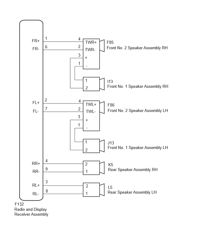
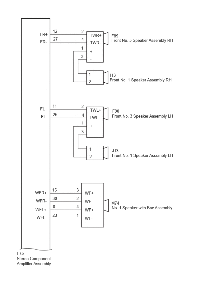
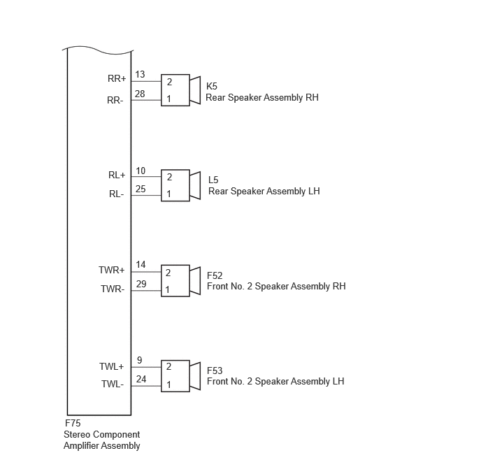
CAUTION / NOTICE / HINT
- NOTICE:
-
Depending on the parts that are replaced during vehicle inspection or maintenance, performing initialization, registration or calibration may be needed.
PROCEDURE
Choose the model to be inspected.
- Result:
Result Proceed to for 6 Speakers A for 9 Speakers B
A
B
Disconnect the F132 radio and display receiver assembly connector.
Disconnect the F85 and F86 front No. 2 speaker assembly connector.
Disconnect the K5 and L5 rear speaker assembly connectors.
Measure the resistance according to the value(s) in the table below.
- Standard Resistance:
Tester Connection Condition Specified Condition F132-1 (FR+) or F85-4 (TWR+) - Body ground Always 10 kΩ or higher F132-6 (FR-) or F85-2 (TWR-) - Body ground Always 10 kΩ or higher F132-2 (FL+) or F86-4 (TWR+) - Body ground Always 10 kΩ or higher F132-7 (FL-) or F86-2 (TWL-) - Body ground Always 10 kΩ or higher F132-4 (RR+) or K5-2 - Body ground Always 10 kΩ or higher F132-9 (RR-) or K5-1 - Body ground Always 10 kΩ or higher F132-3 (RL+) or L5-2 - Body ground Always 10 kΩ or higher F132-8 (RL-) or L5-1 - Body ground Always 10 kΩ or higher
- Result:
Proceed to OK NG
OK
NG
Disconnect the I13 and J13 front No. 1 speaker assembly connectors.
Disconnect the F85 and F86 front No. 2 speaker assembly connectors.
Measure the resistance according to the value(s) in the table below.
- Standard Resistance:
Tester Connection Condition Specified Condition I13-2 or F85-3 (+) - Body ground Always 10 kΩ or higher I13-1 or F85-1 (-) - Body ground Always 10 kΩ or higher J13-2 or F86-3 (+) - Body ground Always 10 kΩ or higher J13-1 or F86-1 (-) - Body ground Always 10 kΩ or higher
- Result:
Proceed to OK NG
OK
NG
Click hereAudio / Visual / Telematics>AUDIO / VIDEO>FRONT DOOR SPEAKER>INSPECTION
- Result:
Proceed to OK NG
OK
NG
Click hereAudio / Visual / Telematics>AUDIO / VIDEO>INSTRUMENT PANEL SPEAKER>INSPECTION
- Result:
Proceed to OK NG
OK
NG
Click hereAudio / Visual / Telematics>AUDIO / VIDEO>REAR DOOR SPEAKER>INSPECTION
- Result:
Proceed to OK NG
OK
NG
Clear the DTCs.
- Body Electrical > Navigation System > Clear DTCs
- 50002 496
Turn the ignition switch off.
Check for DTCs and proceed to the following step.
- Body Electrical > Navigation System > Trouble Codes
- 50001 496
- Result:
Result Proceed to DTCs are not output A DTC B15C371 is output B
A
B
Click hereAudio / Visual / Telematics>AUDIO / VIDEO>RADIO RECEIVER (for Radio and Display Type)>REMOVAL
Disconnect the F75 stereo component amplifier assembly connector.
Disconnect the I13 and J13 front No. 1 speaker assembly connector.
Disconnect the F52 and F53 front No. 2 speaker assembly connector.
Disconnect the F89 and F90 front No. 3 speaker assembly connector.
Disconnect the K5 and L5 rear speaker assembly connectors.
Disconnect the M74 No. 1 speaker with box assembly connector.
Measure the resistance according to the value(s) in the table below.
- Standard Resistance:
Tester Connection Condition Specified Condition F75-12 (FR+) or F89-2 (TWR+) - Body ground Always 10 kΩ or higher F75-27 (FR-) or F89-4 (TWR-) - Body ground Always 10 kΩ or higher F75-11 (FL+) or F90-2 (TWL+) - Body ground Always 10 kΩ or higher F75-26 (FL-) or F90-4 (TWL-) - Body ground Always 10 kΩ or higher F75-15 (WFR+) or M74-3 (WF+) - Body ground Always 10 kΩ or higher F75-30 (WFR-) or M74-2 (WF-) - Body ground Always 10 kΩ or higher F75-8 (WFL+) or M74-4 (WF+) - Body ground Always 10 kΩ or higher F75-23 (WFL-) or M74-1 (WF-) - Body ground Always 10 kΩ or higher F75-13 (RR+) or K5-2 - Body ground Always 10 kΩ or higher F75-28 (RR-) or K5-1 - Body ground Always 10 kΩ or higher F75-10 (RL+) or L5-2 - Body ground Always 10 kΩ or higher F75-25 (RL-) or L5-1 - Body ground Always 10 kΩ or higher F75-14 (TWR+) or F52-2 - Body ground Always 10 kΩ or higher F75-29 (TWR-) or F52-1 - Body ground Always 10 kΩ or higher F75-9 (TWL+) or F53-2 - Body ground Always 10 kΩ or higher F75-24 (TWL-) or F53-1 - Body ground Always 10 kΩ or higher
- Result:
Proceed to OK NG
OK
NG
Disconnect the I13 and J13 front No. 1 speaker assembly connectors.
Disconnect the F89 and F90 front No. 3 speaker assembly connectors.
Measure the resistance according to the value(s) in the table below.
- Standard Resistance:
Tester Connection Condition Specified Condition I13-2 or F89-1 (+) - Body ground Always 10 kΩ or higher I13-1 or F89-3 (-) - Body ground Always 10 kΩ or higher J13-2 or F90-1 (+) - Body ground Always 10 kΩ or higher J13-1 or F90-3 (-) - Body ground Always 10 kΩ or higher
- Result:
Proceed to OK NG
OK
NG
Click hereAudio / Visual / Telematics>AUDIO / VIDEO>FRONT DOOR SPEAKER>INSPECTION
- Result:
Proceed to OK NG
OK
NG
Click hereAudio / Visual / Telematics>AUDIO / VIDEO>INSTRUMENT PANEL SPEAKER>INSPECTION
- Result:
Proceed to OK NG
OK
NG
Click hereAudio / Visual / Telematics>AUDIO / VIDEO>FRONT DOOR SPEAKER>INSPECTION
- Result:
Proceed to OK NG
OK
NG
Click hereAudio / Visual / Telematics>AUDIO / VIDEO>INSTRUMENT PANEL SPEAKER>INSPECTION
- Result:
Proceed to OK NG
OK
NG
Click hereAudio / Visual / Telematics>AUDIO / VIDEO>REAR DOOR SPEAKER>INSPECTION
- Result:
Proceed to OK NG
OK
NG
Clear the DTCs.
- Body Electrical > Navigation System > Clear DTCs
- 50002 496
Turn the ignition switch off.
Check for DTCs and proceed to the following step.
- Body Electrical > Navigation System > Trouble Codes
- 50001 496
- Result:
Result Proceed to DTCs are not output A DTC B15C371 is output B
A
B