NAVIGATION / MULTI INFO DISPLAY NAVIGATION SYSTEM(for Radio and Display Type with Single Knob Type) TERMINALS OF ECU
RADIO AND DISPLAY RECEIVER ASSEMBLY
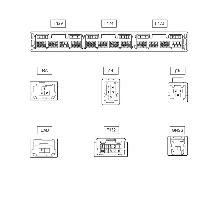
- Standard:
Connector F129 Terminal No. (Symbol) Terminal Description Condition Specified Condition F129-1(GND1) - Body ground Ground Always Below 1 Ω F129-4(+B1) - F129-1(GND1) Power source (+B) Ignition switch off 11 to 14 V F129-7(PKB) - F129-1(GND1) Parking brake signal Ignition switch ON
Parking brake released → Ignition switch ON
Parking brake applied2 V or less → 3 V or higher F129-8(SPD) - F129-1(GND1) Vehicle speed signal Wheel being rotated Waveform 1 F129-12(MUT1) - F129-1(GND1) Mute signal Audio system playing → Mute 3.5 V or higher → Below 1 V F129-15(IG) - F129-1(GND1) Power source (IG) Ignition switch ON 11 to 14 V F129-16(ACC1) - F129-1(GND1) Power source (ACC) Ignition switch ACC 11 to 14 V F129-18(CSWA) - F129-1(GND1) Camera image transition signal Normal → camera image screen change 2 V or less → 6 V or higher F129-20(SWG) - F129-1(GND1) Ground Always Below 1 Ω F129-21(SW1) - F129-1(GND1) Steering pad switch signal No switch pushed → Volume- switch pushed → Volume+ switch pushed → Seek- switch pushed → Seek+ switch pushed 2.7 V or higher → approximately 2.3 V → approximately 1.6 V → approximately 1.0 V → 0.8 V or less F129-22(SW2) - F129-1(GND1) Steering pad switch signal No switch pushed → Voice switch pushed → Off hook switch pushed → On hook switch pushed → MODE switch pushed 2.7 V or higher → approximately 2.3 V → approximately 1.6 V → approximately 1.0 V → 0.8 V or less F129-26(WK2) - F129-1(GND1) Stereo component amplifier assembly start up signal Ignition switch ACC 4 V or higher
Connector F174 Terminal No. (Symbol) Terminal Description Condition Specified Condition F174-1(TX1+) AVC-LAN communication signal - - F174-2(TX1-) AVC-LAN communication signal - - F174-11(CNH1) Local bus communication signal Service Menu - F174-12(CNL1) Local bus communication signal Service Menu - F174-13(CANH) Local bus communication signal Service Menu - F174-14(CANL) Local bus communication signal Service Menu - F174-17(USBG) - Body ground Ground Always Below 1 Ω F174-18(USBV) - F129-1(GND1) Telematics transceiver USB power source Ignition switch ON 3 V or higher F174-21(MIN+) - F129-1(GND1) Microphone voice signal Voice is being input A waveform synchronized with sound signals is output F174-22(MIN-) - F129-1(GND1) Microphone voice signal ground Always Below 1 Ω F174-23(MACC) - F129-1(GND1) Microphone power source or A2B hub power source Ignition switch ON 7.5 to 8.5 V F174-24(SGND) - Body ground Shield ground Always Below 1 Ω F174-25(SNS) - F129-1(GND1) Microphone circuit open detection signal Always Below 1 Ω F174-26(CSLD) - F129-1(GND1) Shield ground Always Below 1 Ω F174-27(CGND) - F129-1(GND1) Ground Always Below 1 Ω F174-28(V+) - F174-29(V-) Video signal (analog) Ignition switch ON, shift lever in R Waveform 2 F174-29(V-) - F129-1(GND1) Video signal (analog) ground Always Below 1 Ω F174-30(CA+) - F129-1(GND1) Rear television camera power source Ignition switch ON 5.8 to 6.5 V
Connector F173 Terminal No. (Symbol) Terminal Description Condition Specified Condition F173-4(FBGN) - F129-1(GND1) Shield ground Always Below 1 Ω F173-15(FB2+) - F129-1(GND1) Stereo component amplifier assembly voice signal 2 Voice is being input A waveform synchronized with sound signals is output F173-16(FB2-) - F129-1(GND1) Stereo component amplifier assembly voice signal 2 Voice is being input A waveform synchronized with sound signals is output F173-27(FB1+) - F129-1(GND1) Stereo component amplifier assembly voice signal 1 Voice is being input A waveform synchronized with sound signals is output F173-28(FB1-) - F129-1(GND1) Stereo component amplifier assembly voice signal 1 Voice is being input A waveform synchronized with sound signals is output
Connector F132 Terminal No. (Symbol) Terminal Description Condition Specified Condition F132-1(FR+) - F129-1(GND1) Sound signal Audio system playing A waveform synchronized with sound signals is output F132-2(FL+) - F129-1(GND1) Sound signal Audio system playing A waveform synchronized with sound signals is output F132-3(RL+) - F129-1(GND1) Sound signal Audio system playing A waveform synchronized with sound signals is output F132-4(RR+) - F129-1(GND1) Sound signal Audio system playing A waveform synchronized with sound signals is output F132-6(FR-) - F129-1(GND1) Sound signal Audio system playing A waveform synchronized with sound signals is output F132-7(FL-) - F129-1(GND1) Sound signal Audio system playing A waveform synchronized with sound signals is output F132-8(RL-) - F129-1(GND1) Sound signal Audio system playing A waveform synchronized with sound signals is output F132-9(RR-) - F129-1(GND1) Sound signal Audio system playing A waveform synchronized with sound signals is output
Connector j16 Terminal No. (Symbol) Terminal Description Condition Specified Condition j16-1(USB+) USB signal - - j16-2(USB-) USB signal - - j16-3(USBS) Shield ground Always Below 1 Ω
Connector j14 Terminal No. (Symbol) Terminal Description Condition Specified Condition j14-1(USV1) Power source Ignition switch ON 4.75 to 5.25 V j14-2(US1-) USB communication signal - - j14-3(US1+) USB communication signal - - j14-4(USD1) Ground Always Below 1 Ω j14-5(USG1) Shield ground Always Below 1 Ω
Connector RA Terminal No. (Symbol) Terminal Description Condition Specified Condition RA-1(ANT+) Radio antenna power source Receiving radio broadcast 7 to 16 V RA-2(SUB) Radio signal (SUB) - - RA-2a(GND) Ground - - RA-3(MAIN) Radio signal (MAIN) - - RA-3a(GND) Ground - -
Connector DAB Terminal No. (Symbol) Terminal Description Condition Specified Condition DAB-1(SUB) DAB signal (SUB) - - DAB-2(MAIN) DAB signal (MAIN) - -
Connector GNSS Terminal No. (Symbol) Terminal Description Condition Specified Condition GNSS-1(GPS) GNSS signal - -
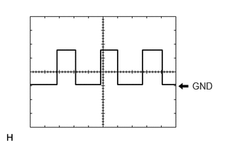
Waveform 1
| Item | Content |
|---|---|
| Measurement terminal | F129-8(SPD) - F129-1(GND1) |
| Measurement setting | 5 V/DIV, 20 ms/DIV |
| Condition | Wheel being rotated |
- HINT:
-
The period changes depending on the rotation speed of the wheels.
Waveform 2
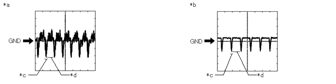
| *a | Waveform A | *b | Waveform B |
| *c | Synchronization Signal | *d | Video Waveform |
| Item | Content |
|---|---|
| Measurement terminal | F174-28(V+) - F174-29(V-) |
| Measurement setting | 0.2 V/DIV, 50 μS/DIV |
| Condition | ·
Waveform A: Rear television camera assembly not covered, ignition switch ON, shift lever in R and image of the area behind the vehicle being displayed ·
Waveform B: Rear television camera assembly covered by hand etc., ignition switch ON, shift lever in R and black screen being displayed |
- NOTICE:
- ·
The video waveform changes according to the image sent by the rear television camera assembly.
·The video waveform is constantly output when the ignition switch is turned to ACC.
STEREO COMPONENT AMPLIFIER ASSEMBLY
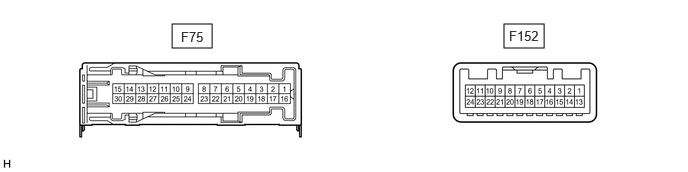
- Standard:
Connector F75 Terminal No. (Symbol) Terminal Description Condition Specified Condition F75-1(+B) - F75-3(GND) Power source (+B) Ignition switch off 11 to 14 V F75-3(GND) - Body ground Ground Always Below 1 Ω F75-8(WFL+) - F75-3(GND) Front sound signal (LH) Audio system playing A waveform synchronized with sound signals is output F75-9(TWL+) - F75-3(GND) Front sound signal (LH) Audio system playing A waveform synchronized with sound signals is output F75-10(RL+) - F75-3(GND) Rear sound signal (LH) Audio system playing A waveform synchronized with sound signals is output F75-11(FL+) - F75-3(GND) Front sound signal (LH) Audio system playing A waveform synchronized with sound signals is output F75-12(FR+) - F75-3(GND) Front sound signal (RH) Audio system playing A waveform synchronized with sound signals is output F75-13(RR+) - F75-3(GND) Rear sound signal (RH) Audio system playing A waveform synchronized with sound signals is output F75-14(TWR+) - F75-3(GND) Front sound signal (RH) Audio system playing A waveform synchronized with sound signals is output F75-15(WFR+) - F75-3(GND) Front sound signal (RH) Audio system playing A waveform synchronized with sound signals is output F75-16(+B2) - F75-3(GND) Power source (+B) Ignition switch off 11 to 14 V F75-18(GND2) - Body ground Ground Always Below 1 Ω F75-23(WFL-) - F75-3(GND) Front sound signal (LH) Audio system playing A waveform synchronized with sound signals is output F75-24(TWL-) - F75-3(GND) Front sound signal (LH) Audio system playing A waveform synchronized with sound signals is output F75-25(RL-) - F75-3(GND) Rear sound signal (LH) Audio system playing A waveform synchronized with sound signals is output F75-26(FL-) - F75-3(GND) Front sound signal (LH) Audio system playing A waveform synchronized with sound signals is output F75-27(FR-) - F75-3(GND) Front sound signal (RH) Audio system playing A waveform synchronized with sound signals is output F75-28(RR-) - F75-3(GND) Rear sound signal (RH) Audio system playing A waveform synchronized with sound signals is output F75-29(TWR-) - F75-3(GND) Front sound signal (RH) Audio system playing A waveform synchronized with sound signals is output F75-30(WFR-) - F75-3(GND) Front sound signal (RH) Audio system playing A waveform synchronized with sound signals is output
Connector F152 Terminal No. (Symbol) Terminal Description Condition Specified Condition F152-1(MUTE) - F75-3(GND) Mute signal Normal → Mute 3.5 V or higher → Below 1 V F152-2(L-) - F75-3(GND) Input voice signal (LH) Voice is being input A waveform synchronized with sound signals is output F152-3(L+) - F75-3(GND) Input voice signal (LH) Voice is being input A waveform synchronized with sound signals is output F152-4(R-) - F75-3(GND) Input voice signal (RH) Voice is being input A waveform synchronized with sound signals is output F152-5(R+) - F75-3(GND) Input voice signal (RH) Voice is being input A waveform synchronized with sound signals is output F152-6(SLD) - Body ground Shield ground Always Below 1 Ω F152-7(TX-) AVC-LAN communication signal Service Menu - F152-8(TX+) AVC-LAN communication signal Service Menu - F152-9(FB1-) - F75-3(GND) Sound signal Audio system playing A waveform synchronized with sound signals is output F152-10(FB1+) - F75-3(GND) Sound signal Audio system playing A waveform synchronized with sound signals is output F152-11(SPD) - F75-3(GND) Vehicle speed signal Wheel being rotated Waveform 1 F152-12(WK2) - F75-3(GND) Stereo component amplifier assembly start signal Ignition switch ACC 4 V or higher F152-13(SLD1) - Body ground Ground Always Below 1 Ω F152-14(ll1-) - F75-3(GND) Input voice signal (LH) Interrupt voice is being input A waveform synchronized with sound signals is output F152-15(ll1+) - F75-3(GND) Input voice signal (LH) Interrupt voice is being input A waveform synchronized with sound signals is output F152-16(ll2-) - F75-3(GND) Input voice signal (LH) Interrupt voice is being input A waveform synchronized with sound signals is output F152-17(ll2+) - F75-3(GND) Input voice signal (LH) Interrupt voice is being input A waveform synchronized with sound signals is output F152-18(SLD2) - Body ground Shield ground Always Below 1 Ω F152-21(FB2-) - F75-3(GND) Sound signal Audio system playing A waveform synchronized with sound signals is output F152-22(FB2+) - F75-3(GND) Sound signal Audio system playing A waveform synchronized with sound signals is output F152-24(TMUT) - F75-3(GND) Mute signal Normal → Mute 3.5 V or higher → Below 1 V
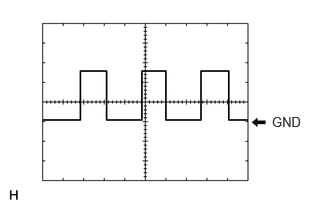
Waveform 1
| Item | Content |
|---|---|
| Measurement terminal | F152-11(SPD) - F75-3(GND) |
| Measurement setting | 5 V/DIV, 20 ms/DIV |
| Condition | Wheel being rotated |
- HINT:
-
The period changes depending on the rotation speed of the wheels.
COMBINATION METER ASSEMBLY
TELEMATICS TRANSCEIVER (for eCall)
- HINT: