RM32K0E
_56
Audio / Visual / Telematics
_084041
TELEMATICS
_0524469
TELEMATICS SYSTEM(for eCall with Single Knob Type Radio and Display)
U
TELEMATICS TELEMATICS SYSTEM(for eCall with Single Knob Type Radio and Display) TERMINALS OF ECU
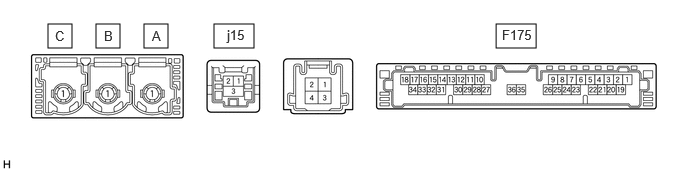
TELEPHONE TRANSCEIVER ASSEMBLY
5.167,0.25 5.583,0.5
0.417,0.25
2.229,0.25 2.646,0.5
0.417,0.25
0.5,0.25 0.75,0.5
0.25,0.25
1,0.25 1.25,0.5
0.25,0.25
1.5,0.25 1.75,0.5
0.25,0.25
5.229,0.281 5.656,0.479
0.427,0.198
10
false
F175
2.365,0.281 2.76,0.521
0.396,0.24
10
false
j15
1.583,0.292 1.76,0.531
0.177,0.24
10
false
A
1.083,0.292 1.26,0.531
0.177,0.24
10
false
B
0.573,0.292 0.75,0.531
0.177,0.24
10
false
C
| Terminal No. (Symbol) | Terminal Description | Condition | Specified Condition |
|---|---|---|---|
| F175-1 (+B) - F175-20 (E) | Power source (+B) | Ignition switch off | 11 to 14 V |
| F175-3 (SIG-) - F175-20 (E) | Ground | Always | Below 1 V |
| F175-4 (IND1) - F175-20 (E) | Mayday switch assembly red indicator illumination signal | For 5 seconds after turning the ignition switch to ON | 1 to 8.5 V |
| Ignition switch off | Below 1 V | ||
| F175-5 (MCVD) - F175-20 (E) | Receive microphone voice signal | Voice being input to built-in microphone of communication telematics box | A waveform synchronized with microphone voice signal is input |
| F175-6 (MCI+) - F175-20 (E) | Receive microphone voice signal | Voice being input to built-in microphone of communication telematics box | A waveform synchronized with microphone voice signal is input |
| F175-7 (MCI-) - F175-20 (E) | Ground | Always | Below 1 V |
| F175-8 (MCMD) - F175-20 (E) | Microphone mode signal | Microphone mode | 0.6 V or higher |
| Emergency call mode | 0.5 V or less | ||
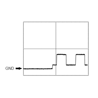
| F175-13 (GSW) - F175-20 (E) | Collision detection signal | Ignition switch ON | Pulse generation
(Refer to waveform 1) |
| F175-14 (MUTE) - F175-20 (E) | MUTE Signal | Audio system playing | Above 3.5 V |
| Emergency call mode | Below 1 V | ||
| F175-15 (USBV) - F175-20 (E)*1 | USB power supply | Ignition switch ON | 4.75 to 5.25 V |
| Ignition switch off | Below 1 V | ||
| F175-18 (SP+) - F175-20 (E) | Sound signal | Sound being output from built-in speaker of communication telematics box | A waveform synchronized with sound signals is output |
| F175-19 (IG2) - F175-20 (E) | Power source (IG) | Ignition switch ON | 11 to 14 V |
| Ignition switch off | Below 1 V | ||
| F175-20 (E) - Body ground | Ground | Always | Below 1 Ω |
| F175-21 (SIG1) - F175-3 (SIG-) | Mayday switch assembly button condition signal | Mayday switch assembly not pressed | 1.3 to 1.9 V |
| Mayday switch assembly pressed | 0.5 to 0.8 V | ||
| F175-22 (IND2) - F175-20 (E) | Mayday switch assembly green indicator illumination signal | For 5 seconds after turning the ignition switch to ON | 1 to 8.5 V |
| Ignition switch off | Below 1 V | ||
| F175-23 (SGND) - F175-20 (E) | Shield ground | Always | Below 1 Ω |
| F175-24 (MICV) - F175-20 (E) | Communication telematics box power supply | Ignition switch ON | 4 to 6 V |
| Ignition switch Off | Below 1 V | ||
| F175-25 (CANP) | CAN communication signal | - | - |
| F175-26 (CANN) | CAN communication signal | - | - |
| F175-30 (SLPD) - F175-20 (E)*2 | Steering lock bar position signal | Steering locked | 11 to 14 V |
| Steering unlocked | Below 1.5 V | ||
| F175-31 (USBG) - Body ground*1 | Shield ground | Always | Below 1 Ω |
| F175-34 (SP-) - F175-20 (E) | Sound signal | Sound being output from built-in speaker of communication telematics box | A waveform synchronized with sound signals is output |
| j15-1 (USB-)*1 | USB communication line | - | - |
| j15-2 (USB+)*1 | USB communication line | - | - |
| j15-3 (USBS) - Body ground*1 | USB communication line | Always | Below 1 Ω |
*1: w/ Navigation System
*2: w/ Smart Entry and Start System
a.
Reference (Oscilloscope waveform):
i.
0.188,2.313 0.583,2.542
0.396,0.229
10
false
GND
Waveform 1
| Item | Condition |
|---|---|
| Tester Connection | F175-13 (GSW) - F175-20 (E) |
| Tool Setting | 5.0 V/DIV., 20 ms./DIV. |
| Vehicle Condition | Ignition switch ON |
RADIO AND DISPLAY RECEIVER ASSEMBLY (w/ Navigation System)