AXLE AND DIFFERENTIAL STEERING KNUCKLE REMOVAL
CAUTION / NOTICE / HINT
The necessary procedures (adjustment, calibration, initialization, or registration) that must be performed after parts are removed and installed, or replaced during steering knuckle removal/installation are shown below.
| Replaced Part or Performed Procedure | Necessary Procedure | Effect/Inoperative Function when Necessary Procedure not Performed | Link |
|---|---|---|---|
| Front wheel alignment adjustment | 1.
Clear zero point calibration data. 2.
Perform yaw rate and acceleration sensor zero point calibration. |
·
DTCs are stored ·
ABS warning light illuminates ·
Slip indicator light illuminates ·
VSC disabled or malfunctions |
( ) |
- HINT:
- ·
Use the same procedure for the RH side and LH side.
·The following procedure is for the LH side.
PROCEDURE

 1.REMOVE FRONT AXLE ASSEMBLY
43340A
2.REMOVE FRONT LOWER BALL JOINT ASSEMBLY
43212
3.REMOVE STEERING KNUCKLE
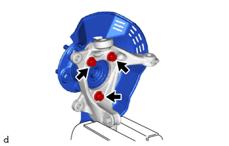
Secure the front axle assembly between aluminum plates in a vise.
- NOTICE:
-
Do not overtighten the vise.
Remove the 3 bolts, front axle hub sub-assembly and front disc brake dust cover from the steering knuckle.
- NOTICE:
- ·
Do not drop the front axle hub sub-assembly.
·Be careful not to damage the speed sensor rotor or contact surfaces.
·Do not allow foreign matter to contact the speed sensor rotor or contact surfaces.