SUPPLEMENTAL RESTRAINT SYSTEMS AIRBAG SYSTEM B1651/33 Manual Cut off Switch Trouble
DESCRIPTION
The airbag cut off switch circuit consists of the airbag sensor assembly and airbag cut off switch cylinder sub-assembly.
The instrument panel passenger without door airbag assembly can be optionally deactivated via this circuit by turning the airbag cut off switch cylinder sub-assembly to the OFF position.
If the instrument panel passenger without door airbag assembly is deactivated, the passenger airbag ON/OFF indicator ("OFF") comes on to inform the driver.
DTC B1651/33 is stored when a malfunction is detected in the airbag cut off switch circuit.
| DTC No. | Detection Item | DTC Detection Condition | Trouble Area | Test Mode / Check Mode |
|---|---|---|---|---|
| B1651/33 | Manual Cut off Switch Trouble | Any of the following conditions is met:
·
The airbag sensor assembly detects a line short, in the airbag cut off switch circuit. ·
The airbag sensor assembly detects a short to ground in the airbag cut off switch circuit. ·
The airbag sensor assembly detects a short to B+ in the airbag cut off switch circuit. ·
The airbag sensor assembly detects an open in the airbag cut off switch circuit. ·
Airbag cut off switch cylinder sub-assembly malfunction ·
Airbag sensor assembly malfunction |
·
Instrument panel wire ·
Airbag cut off switch cylinder sub-assembly ·
Airbag sensor assembly |
Does not apply to test/check mode |
| Vehicle Condition | |||||||
|---|---|---|---|---|---|---|---|
| Pattern 1 | Pattern 2 | Pattern 3 | Pattern 4 | Pattern 5 | Pattern 6 | ||
| Diagnosis Condition | Ignition switch ON | ○ | ○ | ○ | ○ | ○ | ○ |
| Malfunction Status | The airbag sensor assembly detects a line short, in the airbag cut off switch circuit | ○ | - | - | - | - | - |
| The airbag sensor assembly detects a short to ground in the airbag cut off switch circuit | - | ○ | - | - | - | - | |
| The airbag sensor assembly detects a short to B+ in the airbag cut off switch circuit | - | - | ○ | - | - | - | |
| The airbag sensor assembly detects an open in the airbag cut off switch circuit | - | - | - | ○ | - | - | |
| Airbag cut off switch cylinder sub-assembly malfunction | - | - | - | - | ○ | - | |
| Airbag sensor assembly malfunction | - | - | - | - | - | ○ | |
| Detection Time | - | - | - | - | - | - | |
| Number of Trips | 1 trip | 1 trip | 1 trip | 1 trip | 1 trip | 1 trip | |
- HINT:
-
DTC will be output when conditions for either of the patterns in the table above are met.
WIRING DIAGRAM
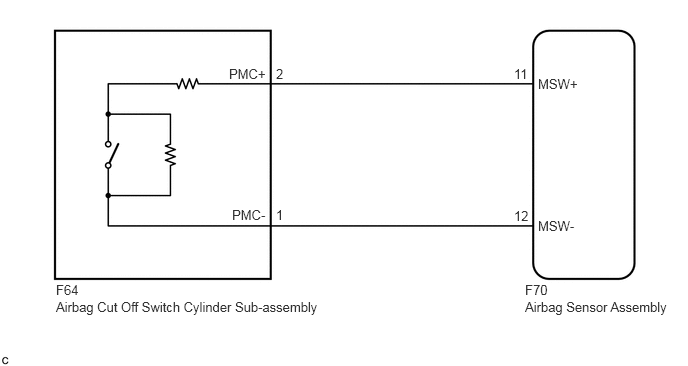
CAUTION / NOTICE / HINT
- NOTICE:
-
After turning the ignition switch off, waiting time may be required before disconnecting the cable from the negative (-) battery terminal. Therefore, make sure to read the disconnecting the cable from the negative (-) battery terminal notices before proceeding with work.
-
Click hereGeneral>INTRODUCTION>REPAIR INSTRUCTION>PRECAUTION
- HINT:
-
Terminals F70-11 (MSW+) and F70-12 (MSW-) of the instrument panel wire in this circuit have an activation prevention mechanism.
-
This mechanism can be used to check for an open circuit in the wire harness. When performing other checks (check for short, short to ground or short to B+), this mechanism should be released.
PROCEDURE
Turn the ignition switch off.
Disconnect the cable from the negative (-) battery terminal.
- CAUTION:
-
Wait at least 90 seconds after disconnecting the cable from the negative (-) battery terminal to disable the SRS system.
Check that the connectors are properly connected to the airbag sensor assembly and airbag cut off switch cylinder sub-assembly.
- OK:
The connectors are properly connected.
- HINT:
-
If the connectors are not properly connected, reconnect the connectors and proceed to the next inspection.
Disconnect the connectors from the airbag sensor assembly and airbag cut off switch cylinder sub-assembly.
Check that the terminals of the connectors are not deformed or damaged.
- OK:
The terminals are not deformed or damaged.
Check that the short springs of the activation prevention mechanism of the instrument panel wire connector are not deformed or damaged.
- OK:
The short springs are not deformed or damaged.
- Result:
Proceed to OK NG
OK
NG
Measure the resistance according to the value(s) in the table below.
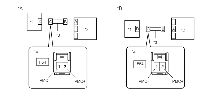
| *A | w/o Dual-stage SRS | *B | w/ Dual-stage SRS |
| *1 | Airbag Cut Off Switch Cylinder Subassembly | *2 | Airbag Sensor Assembly |
| *3 | Instrument Panel Wire | - | - |
| *a | Front view of wire harness connector
(to Airbag Cut Off Switch Cylinder Sub-assembly) |
- | - |
- Standard Resistance:
Tester Connection Condition Specified Condition F64-2 (PMC+) - F64-1 (PMC-) Always Below 1 Ω
- Result:
Proceed to OK NG
OK
NG
Release the activation prevention mechanism built into connector B.
Click hereVehicle Interior>SUPPLEMENTAL RESTRAINT SYSTEMS>AIRBAG SYSTEM>DIAGNOSIS SYSTEM
| *A | w/o Dual-stage SRS | *B | w/ Dual-stage SRS |
| *1 | Airbag Cut Off Switch Cylinder Subassembly | *2 | Airbag Sensor Assembly |
| *3 | Instrument Panel Wire | - | - |
| *a | Front view of wire harness connector
(to Airbag Cut Off Switch Cylinder Sub-assembly) |
- | - |
Measure the resistance according to the value(s) in the table below.
- Standard Resistance:
Tester Connection Condition Specified Condition F64-2 (PMC+) - F64-1 (PMC-) Always 1 MΩ or higher
- Result:
Proceed to OK NG
OK
NG
Connect the cable to the negative (-) battery terminal.
| *A | w/o Dual-stage SRS | *B | w/ Dual-stage SRS |
| *1 | Airbag Cut Off Switch Cylinder Subassembly | *2 | Airbag Sensor Assembly |
| *3 | Instrument Panel Wire | - | - |
| *a | Front view of wire harness connector
(to Airbag Cut Off Switch Cylinder Sub-assembly) |
- | - |
Turn the ignition switch ON.
Measure the voltage according to the value(s) in the table below.
- Standard Voltage:
Tester Connection Switch Condition Specified Condition F64-2 (PMC+) - Body ground Ignition switch ON Below 1 V F64-1 (PMC-) - Body ground Ignition switch ON Below 1 V
Turn the ignition switch off.
Disconnect the cable from the negative (-) battery terminal.
- CAUTION:
-
Wait at least 90 seconds after disconnecting the cable from the negative (-) battery terminal to disable the SRS system.
- Result:
Proceed to OK NG
OK
NG
Measure the resistance according to the value(s) in the table below.
| *A | w/o Dual-stage SRS | *B | w/ Dual-stage SRS |
| *1 | Airbag Cut Off Switch Cylinder Subassembly | *2 | Airbag Sensor Assembly |
| *3 | Instrument Panel Wire | - | - |
| *a | Front view of wire harness connector
(to Airbag Cut Off Switch Cylinder Sub-assembly) |
- | - |
- Standard Resistance:
Tester Connection Condition Specified Condition F64-2 (PMC+) - Body ground Always 1 MΩ or higher F64-1 (PMC-) - Body ground Always 1 MΩ or higher
Restore the released activation prevention mechanism of connector B to the original condition.
- Result:
Proceed to OK NG
OK
NG
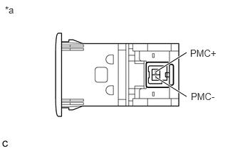
| *a | Component without harness connected
(Airbag Cut Off Switch Cylinder Sub-assembly) |
Measure the resistance according to the value(s) in the table below.
- Standard Resistance:
Tester Connection Condition Specified Condition 2 (PMC+) - 1 (PMC-) Cut off switch in ON position 360 to 440 Ω 2 (PMC+) - 1 (PMC-) Cut off switch in OFF position 90 to 110 Ω
- Result:
Proceed to OK NG
OK
NG
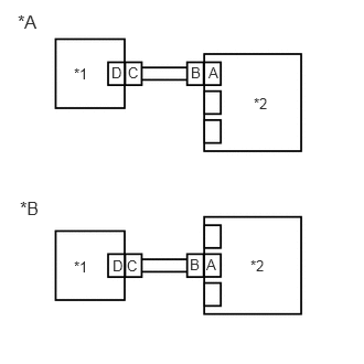
| *A | w/o Dual-stage SRS |
| *B | w/ Dual-stage SRS |
| *1 | Airbag Cut Off Switch Cylinder Sub-assembly |
| *2 | Airbag Sensor Assembly |
Connect the connectors to the airbag sensor assembly and airbag cut off switch cylinder sub-assembly.
Connect the cable to the negative (-) battery terminal.
Clear the DTCs stored in memory.
Click hereVehicle Interior>SUPPLEMENTAL RESTRAINT SYSTEMS>AIRBAG SYSTEM>DTC CHECK / CLEAR
- Body Electrical > SRS Airbag > Clear DTCs
- 50002 188
Turn the ignition switch off.
Turn the ignition switch ON, and wait for at least 60 seconds.
Check for DTCs.
Click hereVehicle Interior>SUPPLEMENTAL RESTRAINT SYSTEMS>AIRBAG SYSTEM>DTC CHECK / CLEAR
- Body Electrical > SRS Airbag > Trouble Codes
- 50001 188
- OK:
DTC B1651/33 is not output.
- HINT:
-
Codes other than DTC B1651/33 may be output at this time, but they are not related to this check.
- Result:
Proceed to OK NG
OK
Click hereGeneral>INTRODUCTION>HOW TO TROUBLESHOOT ECU CONTROLLED SYSTEMS>HOW TO PROCEED WITH TROUBLESHOOTING
NG