Home › Vehicle Interior › SUPPLEMENTAL RESTRAINT SYSTEMS › AIRBAG SYSTEM › 2016.10–2019.09
RM32H0E _58 Vehicle Interior _060061 SUPPLEMENTAL RESTRAINT SYSTEMS _0294190 AIRBAG SYSTEM J

SUPPLEMENTAL RESTRAINT SYSTEMS  AIRBAG SYSTEM  Trouble in Passenger Airbag ON/OFF Indicator  


DESCRIPTION

This circuit detects the airbag cut off switch cylinder sub-assembly status.

The passenger airbag ON/OFF indicator comes on to inform the driver of the instrument panel passenger without door airbag assembly status (activated or deactivated).

HINT:

Approximately 6 seconds after the ignition switch is turned ON, the passenger airbag ON/OFF indicator will indicate ON/OFF depending on the following conditions.

Airbag Cut Off Switch Cylinder Sub-assembly Passenger Airbag ON/OFF Indicator SRS Warning Light
ON Indicator OFF Indicator
ON ON OFF OFF
OFF OFF ON OFF
Switch failure OFF ON ON


WIRING DIAGRAM
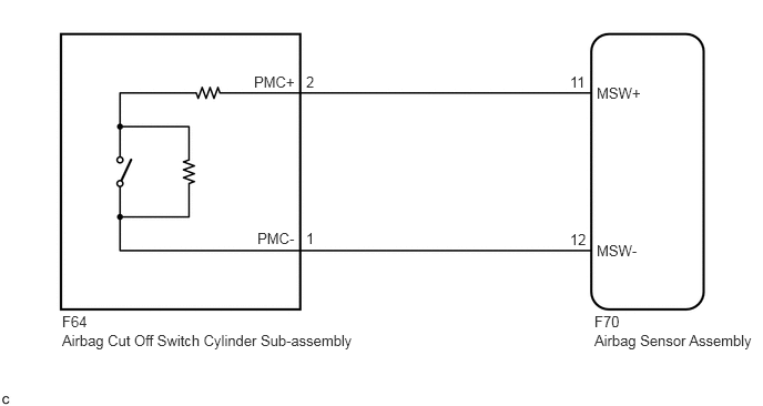
C263693E24
5.354,0.688 5.76,1.042 0.406,0.354 10 false 11 5.354,2.167 5.76,2.521 0.406,0.354 10 false 12 5.604,0.792 6.135,1.167 0.531,0.375 10 false MSW+ 5.604,2.271 6.135,2.646 0.531,0.375 10 false MSW- 5.583,2.938 5.99,3.292 0.406,0.354 10 false F70 5.583,3.115 7.156,3.479 1.573,0.365 10 false Airbag Sensor Assembly 0.583,3.115 3.563,3.438 2.979,0.323 10 false Airbag Cut Off Switch Cylinder Sub-assembly 0.583,2.938 0.99,3.292 0.406,0.354 10 false F64 2.875,0.688 3.281,1.042 0.406,0.354 10 false 2 2.875,2.156 3.281,2.51 0.406,0.354 10 false 1 2.385,0.688 2.865,1.042 0.479,0.354 10 false PMC+ 2.417,2.156 2.896,2.51 0.479,0.354 10 false PMC-

CAUTION / NOTICE / HINT

NOTICE:

After turning the ignition switch off, waiting time may be required before disconnecting the cable from the negative (-) battery terminal. Therefore, make sure to read the disconnecting the cable from the negative (-) battery terminal notices before proceeding with work.

Click hereGeneral>INTRODUCTION>REPAIR INSTRUCTION>PRECAUTION


HINT:

Terminals F70-11 (MSW+) and F70-12 (MSW-) of the instrument panel wire in this circuit have an activation prevention mechanism.

This mechanism can be used to check for an open circuit in the wire harness. When performing other checks (check for short, short to ground or short to B+), this mechanism should be released.


PROCEDURE

1.CHECK SRS WARNING LIGHT
a.

Turn the ignition switch ON, and check the SRS warning light condition.

OK:

After the primary check period, the SRS warning light goes off.


HINT:
·

If the SRS warning light is on when this malfunction occurs, a DTC is stored. Troubleshoot for the stored DTC.

·

The primary check period is approximately 6 seconds after the ignition switch is turned ON.


Result:
Proceed to
OK
NG


OK

2.CHECK CONNECTORS

NG

2.CHECK CONNECTORS
a.

Turn the ignition switch off.


b.

Disconnect the cable from the negative (-) battery terminal.

CAUTION:

Wait at least 90 seconds after disconnecting the cable from the negative (-) battery terminal to disable the SRS system.


c.

Check that the connectors are properly connected to the airbag sensor assembly and airbag cut off switch cylinder sub-assembly.

OK:

The connectors are properly connected.


HINT:

If the connectors are not properly connected, reconnect the connectors and proceed to the next inspection.


d.

Disconnect the connectors from the airbag sensor assembly and airbag cut off switch cylinder sub-assembly.


e.

Check that the terminals of the connectors are not deformed or damaged.

OK:

The terminals are not deformed or damaged.


f.

Check that the short springs of the activation prevention mechanism of the instrument panel wire connector are not deformed or damaged.

OK:

The short springs are not deformed or damaged.


Result:
Proceed to
OK
NG


OK

3.CHECK INSTRUMENT PANEL WIRE (OPEN)

NG

REPLACE INSTRUMENT PANEL WIRE

3.CHECK INSTRUMENT PANEL WIRE (OPEN)
a.

Measure the resistance according to the value(s) in the table below.
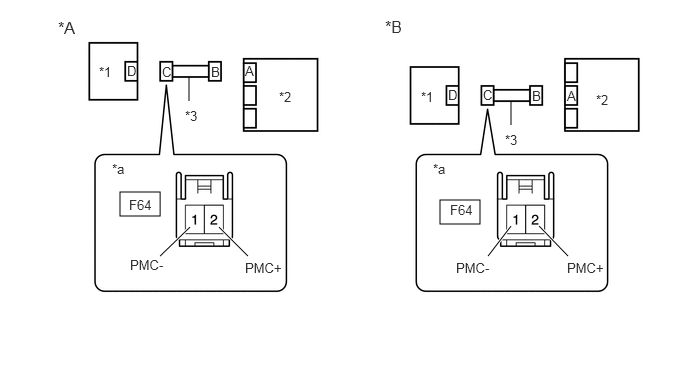
C360609C01
1.25,2 1.667,2.25 0.417,0.25 4.583,2.083 5,2.333 0.417,0.25 1.667,2.667 1.979,2.365 true 2.583,2.667 2.281,2.365 true 5.917,2.667 5.615,2.354 true 5.083,2.667 5.323,2.354 true 1.969,1.052 1.969,0.802 false 5.323,1.302 5.323,1.052 false 0.604,0.188 0.938,0.427 0.333,0.24 12 false *A 4.01,0.177 4.344,0.5 0.333,0.323 12 false *B 1.031,0.667 1.344,0.823 0.313,0.156 10 false *1 2.906,0.927 3.219,1.083 0.313,0.156 10 false *2 5.26,1.375 5.573,1.531 0.313,0.156 10 false *3 1.323,0.656 1.479,0.813 0.156,0.156 10 false D 1.167,1.677 1.479,1.833 0.313,0.156 10 false *a 1.344,2.052 1.833,2.219 0.49,0.167 10 false F64 4.385,0.927 4.698,1.083 0.313,0.156 10 false *1 6.208,0.958 6.521,1.115 0.313,0.156 10 false *2 1.688,0.667 1.844,0.823 0.156,0.156 10 false C 2.198,0.667 2.354,0.823 0.156,0.156 10 false B 2.552,0.656 2.708,0.813 0.156,0.156 10 false A 5.906,0.917 6.063,1.073 0.156,0.156 10 false A 5.542,0.917 5.698,1.073 0.156,0.156 10 false B 5.031,0.906 5.188,1.063 0.156,0.156 10 false C 4.667,0.906 4.823,1.063 0.156,0.156 10 false D 1.927,1.125 2.24,1.281 0.313,0.156 10 false *3 4.51,1.677 4.823,1.833 0.313,0.156 10 false *a 4.688,2.104 5.177,2.271 0.49,0.167 10 false F64 4.75,2.708 5.24,2.875 0.49,0.167 10 false PMC- 1.354,2.677 1.844,2.844 0.49,0.167 10 false PMC- 2.552,2.708 3.042,2.875 0.49,0.167 10 false PMC+ 5.906,2.708 6.396,2.875 0.49,0.167 10 false PMC+
*A w/o Dual-stage SRS *B w/ Dual-stage SRS
*1 Airbag Cut Off Switch Cylinder Sub-assembly *2 Airbag Sensor Assembly
*3 Instrument Panel Wire - -
*a Front view of wire harness connector
(to Airbag Cut Off Switch Cylinder Sub-assembly)
- -


Standard Resistance:
Tester Connection Condition Specified Condition
F64-2 (PMC+) - F64-1 (PMC-) Always Below 1 Ω


Result:
Proceed to
OK
NG


OK

4.CHECK INSTRUMENT PANEL WIRE (SHORT)

NG

REPLACE INSTRUMENT PANEL WIRE

4.CHECK INSTRUMENT PANEL WIRE (SHORT)
a.

Release the activation prevention mechanism built into connector B.

Click hereVehicle Interior>SUPPLEMENTAL RESTRAINT SYSTEMS>AIRBAG SYSTEM>DIAGNOSIS SYSTEM

C360609C01
1.25,2 1.667,2.25 0.417,0.25 4.583,2.083 5,2.333 0.417,0.25 1.667,2.667 1.979,2.365 true 2.583,2.667 2.281,2.365 true 5.917,2.667 5.615,2.354 true 5.083,2.667 5.323,2.354 true 1.969,1.052 1.969,0.802 false 5.323,1.302 5.323,1.052 false 0.604,0.188 0.938,0.427 0.333,0.24 12 false *A 4.01,0.177 4.344,0.5 0.333,0.323 12 false *B 1.031,0.667 1.344,0.823 0.313,0.156 10 false *1 2.906,0.927 3.219,1.083 0.313,0.156 10 false *2 5.26,1.375 5.573,1.531 0.313,0.156 10 false *3 1.323,0.656 1.479,0.813 0.156,0.156 10 false D 1.167,1.677 1.479,1.833 0.313,0.156 10 false *a 1.344,2.052 1.833,2.219 0.49,0.167 10 false F64 4.385,0.927 4.698,1.083 0.313,0.156 10 false *1 6.208,0.958 6.521,1.115 0.313,0.156 10 false *2 1.688,0.667 1.844,0.823 0.156,0.156 10 false C 2.198,0.667 2.354,0.823 0.156,0.156 10 false B 2.552,0.656 2.708,0.813 0.156,0.156 10 false A 5.906,0.917 6.063,1.073 0.156,0.156 10 false A 5.542,0.917 5.698,1.073 0.156,0.156 10 false B 5.031,0.906 5.188,1.063 0.156,0.156 10 false C 4.667,0.906 4.823,1.063 0.156,0.156 10 false D 1.927,1.125 2.24,1.281 0.313,0.156 10 false *3 4.51,1.677 4.823,1.833 0.313,0.156 10 false *a 4.688,2.104 5.177,2.271 0.49,0.167 10 false F64 4.75,2.708 5.24,2.875 0.49,0.167 10 false PMC- 1.354,2.677 1.844,2.844 0.49,0.167 10 false PMC- 2.552,2.708 3.042,2.875 0.49,0.167 10 false PMC+ 5.906,2.708 6.396,2.875 0.49,0.167 10 false PMC+
*A w/o Dual-stage SRS *B w/ Dual-stage SRS
*1 Airbag Cut Off Switch Cylinder Sub-assembly *2 Airbag Sensor Assembly
*3 Instrument Panel Wire - -
*a Front view of wire harness connector
(to Airbag Cut Off Switch Cylinder Sub-assembly)
- -


b.

Measure the resistance according to the value(s) in the table below.

Standard Resistance:
Tester Connection Condition Specified Condition
F64-2 (PMC+) - F64-1 (PMC-) Always 1 MΩ or higher


Result:
Proceed to
OK
NG


OK

5.CHECK INSTRUMENT PANEL WIRE (SHORT TO B+)

NG

REPLACE INSTRUMENT PANEL WIRE

5.CHECK INSTRUMENT PANEL WIRE (SHORT TO B+)
a.

Connect the cable to the negative (-) battery terminal.

C360609C01
1.25,2 1.667,2.25 0.417,0.25 4.583,2.083 5,2.333 0.417,0.25 1.667,2.667 1.979,2.365 true 2.583,2.667 2.281,2.365 true 5.917,2.667 5.615,2.354 true 5.083,2.667 5.323,2.354 true 1.969,1.052 1.969,0.802 false 5.323,1.302 5.323,1.052 false 0.604,0.188 0.938,0.427 0.333,0.24 12 false *A 4.01,0.177 4.344,0.5 0.333,0.323 12 false *B 1.031,0.667 1.344,0.823 0.313,0.156 10 false *1 2.906,0.927 3.219,1.083 0.313,0.156 10 false *2 5.26,1.375 5.573,1.531 0.313,0.156 10 false *3 1.323,0.656 1.479,0.813 0.156,0.156 10 false D 1.167,1.677 1.479,1.833 0.313,0.156 10 false *a 1.344,2.052 1.833,2.219 0.49,0.167 10 false F64 4.385,0.927 4.698,1.083 0.313,0.156 10 false *1 6.208,0.958 6.521,1.115 0.313,0.156 10 false *2 1.688,0.667 1.844,0.823 0.156,0.156 10 false C 2.198,0.667 2.354,0.823 0.156,0.156 10 false B 2.552,0.656 2.708,0.813 0.156,0.156 10 false A 5.906,0.917 6.063,1.073 0.156,0.156 10 false A 5.542,0.917 5.698,1.073 0.156,0.156 10 false B 5.031,0.906 5.188,1.063 0.156,0.156 10 false C 4.667,0.906 4.823,1.063 0.156,0.156 10 false D 1.927,1.125 2.24,1.281 0.313,0.156 10 false *3 4.51,1.677 4.823,1.833 0.313,0.156 10 false *a 4.688,2.104 5.177,2.271 0.49,0.167 10 false F64 4.75,2.708 5.24,2.875 0.49,0.167 10 false PMC- 1.354,2.677 1.844,2.844 0.49,0.167 10 false PMC- 2.552,2.708 3.042,2.875 0.49,0.167 10 false PMC+ 5.906,2.708 6.396,2.875 0.49,0.167 10 false PMC+
*A w/o Dual-stage SRS *B w/ Dual-stage SRS
*1 Airbag Cut Off Switch Cylinder Sub-assembly *2 Airbag Sensor Assembly
*3 Instrument Panel Wire - -
*a Front view of wire harness connector
(to Airbag Cut Off Switch Cylinder Sub-assembly)
- -


b.

Turn the ignition switch ON.


c.

Measure the voltage according to the value(s) in the table below.

Standard Voltage:
Tester Connection Switch Condition Specified Condition
F64-2 (PMC+) - Body ground Ignition switch ON Below 1 V
F64-1 (PMC-) - Body ground Ignition switch ON Below 1 V


d.

Turn the ignition switch off.


e.

Disconnect the cable from the negative (-) battery terminal.

CAUTION:

Wait at least 90 seconds after disconnecting the cable from the negative (-) battery terminal to disable the SRS system.


Result:
Proceed to
OK
NG


OK

6.CHECK INSTRUMENT PANEL WIRE (SHORT TO GROUND)

NG

REPLACE INSTRUMENT PANEL WIRE

6.CHECK INSTRUMENT PANEL WIRE (SHORT TO GROUND)
a.

Measure the resistance according to the value(s) in the table below.

C360609C01
1.25,2 1.667,2.25 0.417,0.25 4.583,2.083 5,2.333 0.417,0.25 1.667,2.667 1.979,2.365 true 2.583,2.667 2.281,2.365 true 5.917,2.667 5.615,2.354 true 5.083,2.667 5.323,2.354 true 1.969,1.052 1.969,0.802 false 5.323,1.302 5.323,1.052 false 0.604,0.188 0.938,0.427 0.333,0.24 12 false *A 4.01,0.177 4.344,0.5 0.333,0.323 12 false *B 1.031,0.667 1.344,0.823 0.313,0.156 10 false *1 2.906,0.927 3.219,1.083 0.313,0.156 10 false *2 5.26,1.375 5.573,1.531 0.313,0.156 10 false *3 1.323,0.656 1.479,0.813 0.156,0.156 10 false D 1.167,1.677 1.479,1.833 0.313,0.156 10 false *a 1.344,2.052 1.833,2.219 0.49,0.167 10 false F64 4.385,0.927 4.698,1.083 0.313,0.156 10 false *1 6.208,0.958 6.521,1.115 0.313,0.156 10 false *2 1.688,0.667 1.844,0.823 0.156,0.156 10 false C 2.198,0.667 2.354,0.823 0.156,0.156 10 false B 2.552,0.656 2.708,0.813 0.156,0.156 10 false A 5.906,0.917 6.063,1.073 0.156,0.156 10 false A 5.542,0.917 5.698,1.073 0.156,0.156 10 false B 5.031,0.906 5.188,1.063 0.156,0.156 10 false C 4.667,0.906 4.823,1.063 0.156,0.156 10 false D 1.927,1.125 2.24,1.281 0.313,0.156 10 false *3 4.51,1.677 4.823,1.833 0.313,0.156 10 false *a 4.688,2.104 5.177,2.271 0.49,0.167 10 false F64 4.75,2.708 5.24,2.875 0.49,0.167 10 false PMC- 1.354,2.677 1.844,2.844 0.49,0.167 10 false PMC- 2.552,2.708 3.042,2.875 0.49,0.167 10 false PMC+ 5.906,2.708 6.396,2.875 0.49,0.167 10 false PMC+
*A w/o Dual-stage SRS *B w/ Dual-stage SRS
*1 Airbag Cut Off Switch Cylinder Sub-assembly *2 Airbag Sensor Assembly
*3 Instrument Panel Wire - -
*a Front view of wire harness connector
(to Airbag Cut Off Switch Cylinder Sub-assembly)
- -


Standard Resistance:
Tester Connection Condition Specified Condition
F64-2 (PMC+) - Body ground Always 1 MΩ or higher
F64-1 (PMC-) - Body ground Always 1 MΩ or higher


b.

Restore the released activation prevention mechanism of connector B to the original condition.


Result:
Proceed to
OK
NG


OK

7.CHECK AIRBAG CUT OFF SWITCH CYLINDER SUB-ASSEMBLY

NG

REPLACE INSTRUMENT PANEL WIRE

7.CHECK AIRBAG CUT OFF SWITCH CYLINDER SUB-ASSEMBLY
a.
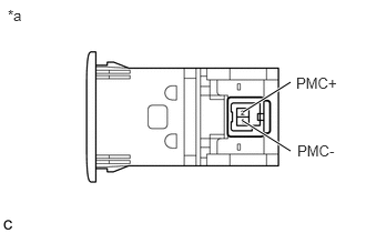
C261687C16
2.281,1.052 2.729,0.771 true 2.281,1.135 2.729,1.417 true 0.073,0.063 0.354,0.365 0.281,0.302 10 false *a 2.781,0.698 3.25,1.042 0.469,0.344 10 false PMC+ 2.792,1.333 3.26,1.677 0.469,0.344 10 false PMC-
*a Component without harness connected
(Airbag Cut Off Switch Cylinder Sub-assembly)


Measure the resistance according to the value(s) in the table below.

Standard Resistance:
Tester Connection Condition Specified Condition
2 (PMC+) - 1 (PMC-) Cut off switch in ON position 360 to 440 Ω
2 (PMC+) - 1 (PMC-) Cut off switch in OFF position 90 to 110 Ω


Result:
Proceed to
OK
NG


OK

NG

REPLACE AIRBAG CUT OFF SWITCH CYLINDER SUB-ASSEMBLY