REAR SUSPENSION REAR SUSPENSION MEMBER(for AWD) INSTALLATION
PROCEDURE

 1.INSTALL HOLE PLUG
Install the 8 hole plugs to the rear suspension member sub-assembly.
51284
2.INSTALL REAR SUSPENSION MEMBER HOLE COVER
Install the 4 rear suspension member hole covers to the rear suspension member sub-assembly.
41651
3.INSTALL REAR NO. 1 DIFFERENTIAL MOUNT CUSHION
Using SST, install a new rear No. 1 differential mount cushion.
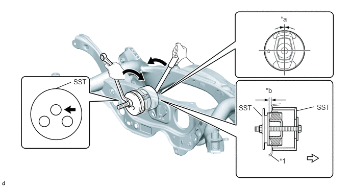
| *1 | Rear Suspension Member Sub-assembly | - | - |
| *a | 0° +/- 3° | *b | 5.0 to 6.0 mm (0.197 to 0.236 in.) |

|
SST bolt location | 
|
Front of the Vehicle |
- SST
- 09316-12010 09570-24011
- NOTICE:
- ·
Make sure that the rear No. 1 differential mount cushion is aligned within 3° from the center.
·Temporarily install the rear No. 1 differential mount cushion to the rear suspension member sub-assembly in order to prevent it from tilting, and then install SST.
·Before using SST, apply grease to the SST bolts.
·Be sure to use the correct combination of SST.
·Make sure that SST (09316-12010) contacts the entire circumference of the rear No. 1 differential mount cushion.
·Do not tilt the bolts of SST.
- HINT:
-
Install the SST bolt to the SST hole as shown in the illustration.
48790
4.INSTALL REAR UPPER CONTROL ARM ASSEMBLY LH
48770A
5.INSTALL REAR UPPER CONTROL ARM ASSEMBLY RH
- HINT:
-
Perform the same procedure as for the LH side.
51206A
6.INSTALL REAR SUSPENSION MEMBER SUB-ASSEMBLY
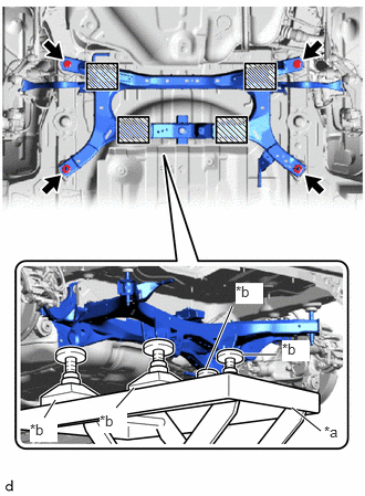
| *a | Engine Lifter |
| *b | Attachment |

|
Attachment and Wooden Block Placement Location |
Using an engine lifter and 4 attachments or equivalent tools, support the rear suspension member sub-assembly as shown in the illustration.
- CAUTION:
-
- ·
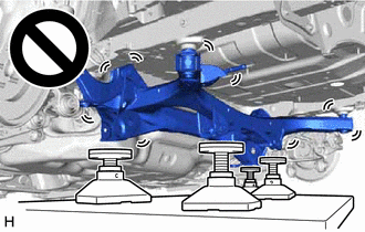
The rear suspension member sub-assembly is a very heavy component. Make sure that it is supported securely.
·If the rear suspension member sub-assembly is not securely supported, it may drop, resulting in serious injury.
- NOTICE:
- ·
Use attachments and wooden blocks to keep the rear suspension member sub-assembly level.
·Keep supporting the rear suspension member sub-assembly until the installation has been completed.
Raise the rear suspension member sub-assembly until there is no clearance between the rear suspension member sub-assembly and vehicle.
Install the rear suspension member sub-assembly with the 2 bolts and 2 nuts.
- Torque:
- 143 N*m (1458 kgf*cm, 105 ft.*lbf)
Engage the 3 clamps to install the differential carrier wire harness.
w/ Height Control Sensor:
Engage the clamp to install the height control sensor wire harness.
48812
7.INSTALL REAR STABILIZER BAR
41101
8.INSTALL REAR DIFFERENTIAL CARRIER SUB-ASSEMBLY
9.INSPECT AND ADJUST REAR WHEEL ALIGNMENT
10.PERFORM INITIALIZATION
11.PERFORM CALIBRATION
·
Parking support brake system ·
Simple intelligent parking assist system |
( ) |
| Panoramic view monitor system | ()
|