LIGHTING (EXT) LIGHTING SYSTEM(w/ Headlight ECU) U0242 Lost Communication With Headlamp Control Module "B"
DESCRIPTION
The headlight ECU sub-assembly LH stores this DTC when the headlight ECU sub-assembly RH detects an internal malfunction or if a communication malfunction occurs between headlight ECU sub-assembly LH and headlight ECU sub-assembly RH for 10 seconds or more.
| DTC No. | Detection Item | DTC Detection Condition | Trouble Area | Note |
|---|---|---|---|---|
| U0242 | Lost Communication With Headlamp Control Module "B" | Any of the following conditions is met:
·
Headlight ECU sub-assembly RH internal malfunction ·
Communication malfunction occurs between headlight ECU sub-assembly LH and headlight ECU sub-assembly RH for 10 seconds or more |
·
Headlight ECU sub-assembly LH ·
Headlight ECU sub-assembly RH ·
Harness or connector |
- |
| Vehicle Condition | |||
|---|---|---|---|
| Pattern 1 | Pattern 2 | ||
| Diagnosis Condition | Ignition switch ON | ○ | ○ |
| Malfunction Status | Headlight ECU sub-assembly RH internal malfunction | ○ | - |
| Communication malfunction occurs between headlight ECU sub-assembly LH and headlight ECU sub-assembly RH | - | ○ | |
| Detection Time | - | 10 seconds or more | |
| Number of Trips | 1 trip | 1 trip | |
- HINT:
-
DTC will be output when conditions for either of the patterns in the table above are met.
WIRING DIAGRAM
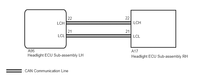
CAUTION / NOTICE / HINT
- NOTICE:
-
If the headlight ECU sub-assembly LH has been replaced, it is necessary to synchronize the vehicle information and initialize the headlight ECU sub-assembly LH.
-
Click hereVehicle Exterior>LIGHTING (EXT)>LIGHTING SYSTEM (w/ Headlight ECU)>INITIALIZATION
PROCEDURE
Connect the GTS to the DLC3.
Turn the ignition switch to ON.
Turn the GTS on.
Enter the following menus: Body Electrical / AFS / Clear DTCs.
Clear the DTCs.
- Body Electrical > AFS > Clear DTCs
- 50002 165
- Result:
Proceed to NEXT
NEXT
Connect the GTS to the DLC3.
Turn the ignition switchi to ON.
Turn the GTS on.
Enter the following menus: Body Electrical / AFS / Trouble Codes.
Check for DTCs.
- Body Electrical > AFS > Trouble Codes
- 50001 165
- OK:
DTC U0242 is not output.
- Result:
Proceed to OK NG
OK
Click hereGeneral>INTRODUCTION>HOW TO TROUBLESHOOT ECU CONTROLLED SYSTEMS>HOW TO PROCEED WITH TROUBLESHOOTING
NG
Turn the ignition switch off.
Disconnect the cable from the negative (-) auxiliary battery terminal.
Disconnect the A95 headlight ECU sub-assembly LH connector.
Measure the resistance according to the value(s) in the table below.
- Standard Resistance:
Tester Connection Condition Specified Condition Result A95-21 (LCL) - A95-22 (LCH) Cable disconnected from negative (-) auxiliary battery terminal 108 to 132 Ω 132 Ω or more:
Open circuit in main bus linesBelow 108 Ω:
Short circuit between bus linesA95-21 (LCL) - GND Cable disconnected from negative (-) auxiliary battery terminal 200 Ω or higher Below 200 Ω:
LCL short to groundA95-22 (LCH) - GND Cable disconnected from negative (-) auxiliary battery terminal 200 Ω or higher Below 200 Ω:
LCH short to groundA95-21 (LCL) - +B Cable disconnected from negative (-) auxiliary battery terminal 6 kΩ or higher Below 6 kΩ:
LCL +B shortA95-22 (LCH) - +B Cable disconnected from negative (-) auxiliary battery terminal 6 kΩ or higher Below 6 kΩ:
LCH +B short
- Result:
Result Proceed to OK A NG (Open circuit in main lines) B NG (Short circuit between main lines) C NG (Short to +B or ground) D
A
B
C
D
Connect the A95 headlight ECU sub-assembly LH connector.
Disconnect the A17 headlight ECU sub-assembly RH connector.
Measure the resistance according to the value(s) in the table below.
- Standard Resistance:
Tester Connection Condition Specified Condition A17-21 (LCL) - A17-22 (LCH) Cable disconnected from negative (-) auxiliary battery terminal 108 to 132 Ω
- Result:
Proceed to OK NG
OK
NG
Connect the A95 headlight ECU sub-assembly LH connector.
Disconnect the A17 headlight ECU sub-assembly RH connector.
Measure the resistance according to the value(s) in the table below.
- Standard Resistance:
Tester Connection Condition Specified Condition A17-21 (LCL) - A17-22 (LCH) Cable disconnected from negative (-) auxiliary battery terminal 108 to 132 Ω
- Result:
Proceed to OK NG
OK
NG
Disconnect the A17 headlight ECU sub-assembly RH connector.
Measure the resistance according to the value(s) in the table below.
- Standard Resistance:
Tester Connection Condition Specified Condition A17-21 (LCL) - GND Cable disconnected from negative (-) auxiliary battery terminal 200 Ω or higher A17-22 (LCH) - GND Cable disconnected from negative (-) auxiliary battery terminal 200 Ω or higher A17-21 (LCL) - +B Cable disconnected from negative (-) auxiliary battery terminal 6 kΩ or higher A17-22 (LCH) - +B Cable disconnected from negative (-) auxiliary battery terminal 6 kΩ or higher
- Result:
Proceed to OK NG
OK
NG
Replace the headlight ECU sub-assembly RH with a new or known good one.
Click hereVehicle Exterior>LIGHTING (EXT)>HEADLIGHT ECU>REMOVAL
- Result:
Proceed to NEXT
NEXT
Connect the GTS to the DLC3.
Turn the ignition switch to ON.
Turn the GTS on.
Enter the following menus: Body Electrical / AFS / Clear DTCs.
Clear the DTCs.
- Body Electrical > AFS > Clear DTCs
- 50002 165
- Result:
Proceed to NEXT
NEXT
Connect the GTS to the DLC3.
Turn the ignition switch to ON.
Turn the GTS on.
Enter the following menus: Body Electrical / AFS / Trouble Codes.
Check for DTCs.
- Body Electrical > AFS > Trouble Codes
- 50001 165
- OK:
DTC U0242 is not output.
- Result:
Proceed to OK NG
OK
NG