8NR-FTS FUEL FUEL PUMP ECU REMOVAL
CAUTION / NOTICE / HINT
The necessary procedures (adjustment, calibration, initialization or registration) that must be performed after parts are removed and installed, or replaced during fuel pump control ECU assembly removal/installation are shown below.
| Replaced Part or Performed Procedure | Necessary Procedure | Effect/Inoperative Function when Necessary Procedure not Performed | Link |
|---|---|---|---|
| Disconnect cable from negative battery terminal | Memorize steering angle neutral point | Panoramic view monitor system | ( ) |
- HINT:
-
When the cable is disconnected / reconnected to the battery terminal, systems temporarily stop operating. However, each system has a function that completes learning the first time the system is used.
- ·
Learning completes when vehicle is driven
Effect/Inoperative Function When Necessary Procedures are not Performed Necessary Procedures Link *1: When performing learning using the GTS
Click here(
)
Lane tracing assist system Drive the vehicle straight ahead at 35 km/h (22 mph) or more for 5 second or more. ( )
Pre-collision system Simple intelligent parking assist system*1 Parking support brake system*1
·Learning completes when vehicle is operated normally
Effect/Inoperative Function When Necessary Procedures are not Performed Necessary Procedures Link Power door lock control system
·Back door opener
Perform door unlock operation with door control switch or electrical key transmitter sub-assembly switch. ( )
Air conditioning system After the ignition switch is turned to ON, the servo motor standard position is recognized. -
PROCEDURE

 1. PRECAUTION
- NOTICE:
-
After turning the ignition switch off, waiting time may be required before disconnecting the cable from the negative (-) battery terminal.
-
Click hereGeneral>INTRODUCTION>REPAIR INSTRUCTION>PRECAUTION
2.DISCONNECT CABLE FROM NEGATIVE BATTERY TERMINAL
3.REMOVE REAR SEATBACK ASSEMBLY LH
4.REMOVE BENCH TYPE REAR SEAT CUSHION ASSEMBLY
72693
5.REMOVE REAR SEAT CUSHION LOCK HOOK
64330D
6.REMOVE PACKAGE TRAY TRIM PANEL ASSEMBLY (w/ Package Tray Trim)
64910J
7.REMOVE TONNEAU COVER ASSEMBLY (w/ Tonneau Cover)
58410B
8.REMOVE DECK BOARD ASSEMBLY
64777J
9.REMOVE SPARE WHEEL CUSHION
64997
10.REMOVE DECK FLOOR BOX LH (w/ Deck Floor Box)
62332A
11.SEPARATE REAR DOOR OPENING TRIM WEATHERSTRIP LH
Separate the rear door opening trim weatherstrip LH.
67918A
12.REMOVE REAR DOOR SCUFF PLATE LH
71304C
13.REMOVE REAR SEATBACK HINGE SUB-ASSEMBLY LH
62552F
14.REMOVE REAR SEAT SIDE GARNISH LH
64716D
15.REMOVE DECK TRIM REAR COVER
81330
16.REMOVE NO. 1 LUGGAGE COMPARTMENT LIGHT ASSEMBLY
64740C
17.REMOVE DECK TRIM SIDE PANEL ASSEMBLY LH
89570A
18.REMOVE FUEL PUMP CONTROL ECU ASSEMBLY
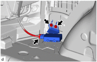
Disconnect the fuel pump control ECU assembly connector.
Remove the 2 bolts and fuel pump control ECU assembly.
- NOTICE:
-
Do not reuse the fuel pump control ECU assembly if it has been dropped or subjected to a severe impact.
- HINT:
-
If a malfunction such as pump lock occurs and the fuel pump is damaged, excessive current may be continuously applied to the fuel pump control ECU assembly, damaging its internal parts. Make sure to replace the fuel pump control ECU assembly at the same time when replacing the fuel pump.