GF1A TRANSFER / 4WD / AWD TRANSFER ASSEMBLY REMOVAL
CAUTION / NOTICE / HINT
The necessary procedures (adjustment, calibration, initialization, or registration) that must be performed after parts are removed and installed, or replaced during transfer assembly removal/installation are shown below.
| Replacement Part or Procedure | Necessary Procedure | Effect/Inoperative when not Performed | Link |
|---|---|---|---|
| Disconnect cable from negative battery terminal | Memorize steering angle neutral point | Panoramic view monitor system | ( ) |
| Front wheel alignment adjustment | Perform the following procedures in the order shown:
1.
Clear zero point calibration data and store system information 2.
Perform yaw rate and acceleration sensor zero point calibration and store system information |
·
VSC disabled or malfunctions ·
Slip indicator light illuminates ·
ABS warning light illuminates |
()
|
| Suspension, tires, etc.
(The vehicle height changes because of suspension or tire replacement) |
Initialize headlight ECU sub-assembly LH | Automatic headlight beam level control system | ()
|
- CAUTION:
- ·
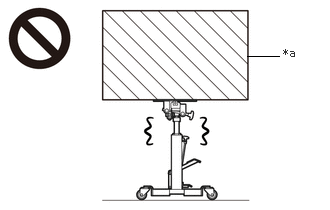 2.573,0.583 2.906,0.583 false 2.948,0.479 3.26,0.677 0.313,0.198 10 false *a
*a Heavy object exceeding the capacity of the transmission jack
Because the continuously variable transaxle assembly is extremely heavy, make sure to follow the work procedures described in the repair manual.
·If work is not performed according to the procedures described in the repair manual, there is a danger that the transmission jack could drop and components could fall down.
- ·
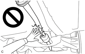
When the engine is hot, do not touch high-temperature areas such as the engine or exhaust pipe.
·Touching high-temperature areas such as the engine and exhaust pipe could result in burns.
CAUTION / NOTICE / HINT
- HINT:
-
When the cable is disconnected / reconnected to the battery terminal, systems temporarily stop operating. However, each system has a function that completes learning the first time the system is used.
- ·
Learning completes when vehicle is driven
Effect/Inoperative Function When Necessary Procedures are not Performed Necessary Procedures Link *1: When performing learning using the GTS
(
)
Lane tracing assist system Drive the vehicle straight ahead at 35 km/h (22 mph) or more for 5 second or more. ( )
Pre-collision system Simple intelligent parking assist system*1 Parking support brake system*1
·Learning completes when vehicle is operated normally
Effect/Inoperative Function When Necessary Procedures are not Performed Necessary Procedures Link Power door lock control system
·Back door opener
Perform door unlock operation with door control switch or electrical key transmitter sub-assembly switch. ( )
Air conditioning system After the ignition switch is turned to ON, the servo motor standard position is recognized. -
PROCEDURE

 30400
1.REMOVE CONTINUOUSLY VARIABLE TRANSAXLE ASSEMBLY
36100
2.REMOVE TRANSFER ASSEMBLY
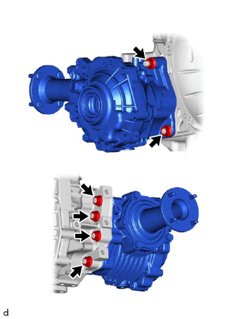
Remove the 6 nuts and transfer assembly from the transaxle.
36100A
3.REMOVE TRANSFER AND TRANSAXLE SETTING STUD BOLT
- HINT:
-
It is not necessary to remove the transfer and transaxle setting stud bolts unless they are being replaced.
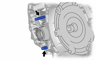
Remove the 2 transfer and transaxle setting stud bolts.