B1423/23 Pressure Sensor Circuit
Diagnostic trouble codes · Vehicles built from Jun 2006
DESCRIPTION
This DTC is output when refrigerant pressure is extremely low (0.19 MPa (2.0 kgf/cm2, 28 psi) or less) or extremely high (3.14 MPa (32.0 kgf/cm2, 455 psi) or more). The pressure sensor, which is installed on the pipe of the high pressure side to detect refrigerant pressure, outputs a refrigerant pressure signal to the A/C amplifier. The A/C amplifier converts this signal to pressure according to the sensor characteristics to control the compressor.- HINT:
- Be sure to check the refrigerant volume first when this DTC is output because this DTC can also be output if there is no refrigerant in the system.
| DTC No. |
DTC Detection Condition |
Trouble Area |
| B1423/23 |
Open or short in pressure sensor circuit |
|
WIRING DIAGRAM
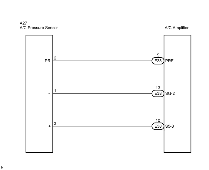

INSPECTION PROCEDURE
| 1. CHECK REFRIGERANT PRESSURE |

Install the manifold gauge set (Click here).
Read the manifold gauge pressure when the following conditions are established.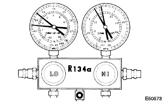
Prepare the vehicle according to the chart below.
Item
Condition
Vehicle Doors
Fully open
Temperature Setting
MAX COLD
Blower Speed
HI
A/C Switch
ON
R/F Switch
RECIRCULATION
(30 to 35°C (86 to 95°F))
- Standard pressure:
- Low pressure side:
- 0.15 to 0.25 MPa (1.5 to 2.5 kgf/cm2, 21.3 to 35.6 psi)
- High pressure side:
- 1.37 to 1.57 MPa (14 to 16 kgf/cm2, 199 to 228 psi)
|
|
||||

| OK | |
 |
| 2. CHECK HARNESS AND CONNECTOR (PRESSURE SENSOR - A/C AMPLIFIER) |
Disconnect the pressure sensor connector.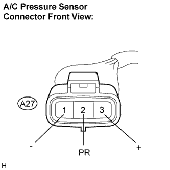
Disconnect the A/C amplifier connector.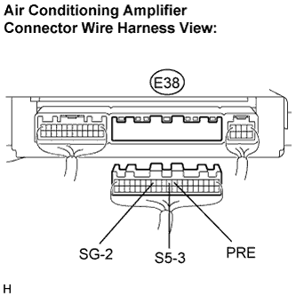
Measure the resistance according to the value(s) in the table below.
- Standard resistance:
Tester Connection
Condition
Specified Condition
A27-2 (PR) - E38-9 (PRE)
Always
Below 1 Ω
A27-3 (+) - E38-10 (S5-3)
Always
Below 1 Ω
A27-1 (-) - E38-13 (SG-2)
Always
Below 1 Ω
E38-9 (PRE) - Body ground
Always
10 kΩ or higher
E38-10 (S5-3) - Body ground
Always
10 kΩ or higher
E38-13 (SG-2) - Body ground
Always
10 kΩ or higher
|
|
||||
| OK | |
|
| 3. INSPECT PRESSURE SENSOR |
Install the manifold gauge set (Click here).
Connect the three 1.5 V dry cell batteries' positive (+) lead to terminal 3, and the negative (-) lead to terminal 1. Then connect the voltmeter's positive (+) lead to terminal 2, and the negative (-) lead to terminal 1. Measure the voltage.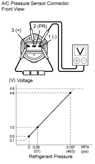
- OK:
- The voltage changes according to refrigerant pressure, as shown in the graph.
- Result:
Result
Proceed to
NG
A
OK (When troubleshooting according to the DTC)
B
OK (When troubleshooting according to the PROBLEM SYMPTOMS TABLE)
C
|
|
||||
|
|
||||
| A | ||
 |
||
| ||