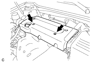
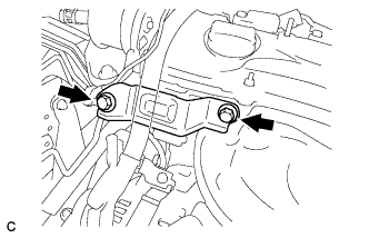
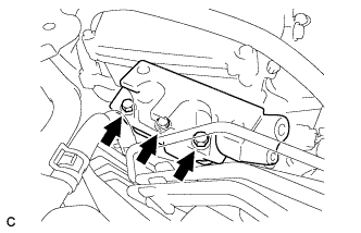
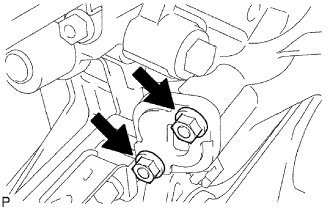
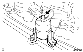
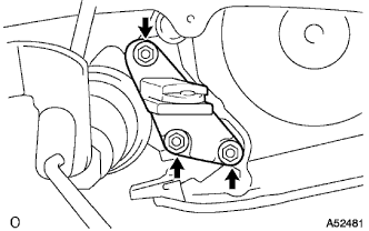
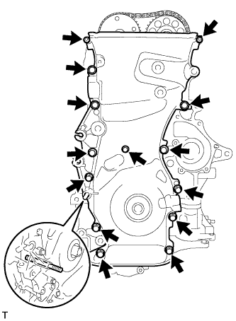
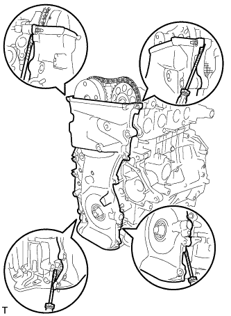
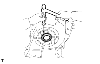
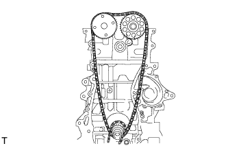
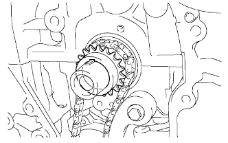
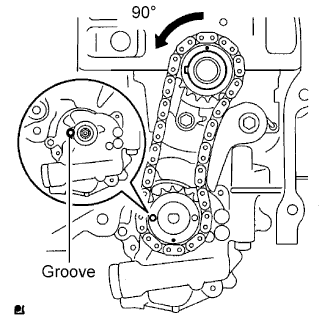
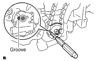
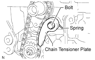
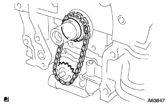
Remove the 2 bolts and No. 2 engine mounting stay RH.
10.
REMOVE ENGINE MOVING CONTROL ROD SUB-ASSEMBLY
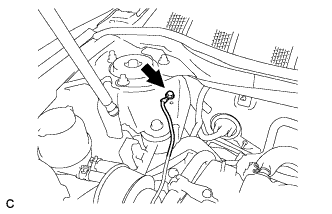
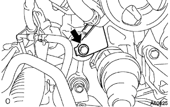
Remove the bolt and disconnect the ground cable.
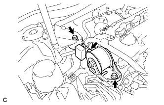
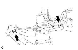
Remove the 3 bolts and the engine moving control rod sub-assembly.
11.
REMOVE NO. 2 ENGINE MOUNTING BRACKET RH
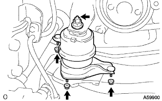
Remove the 3 bolts and No. 2 engine mounting bracket RH.
12.
REMOVE V-RIBBED BELT
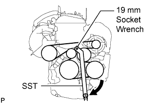
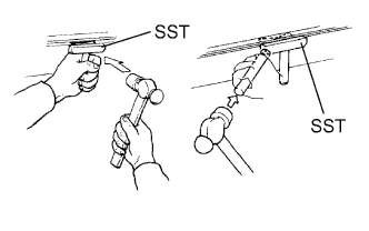
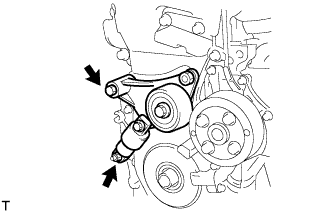
Using SST and a 19 mm socket wrench, loosen the V-ribbed belt tensioner arm clockwise, then remove the V-ribbed belt.
SST
09216-42010
NOTICE:
Be sure to connect SST and the tools so that they are in line during use.
When retracting the tensioner, turn it clockwise slowly for 3 seconds or more. Do not apply force rapidly.
After the tensioner is fully retracted, do not apply more force than necessary.
13.
REMOVE GENERATOR ASSEMBLY
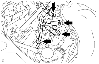
Disconnect the generator connector.
Remove the nut and disconnect the wire harness from terminal B.
Remove the bolt and wire harness clamp bracket.
Remove the wire harness clamp.
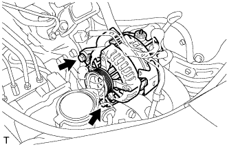
Remove the 2 bolts and generator assembly.
14.
REMOVE VANE PUMP ASSEMBLY
Disconnect the oil pressure switch connector.
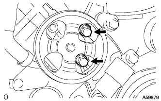
Loosen the 2 bolts and remove the vane pump from the engine.
15.
REMOVE IGNITION COIL ASSEMBLY
Remove the 4 bolts and 4 ignition coils.
16.
DISCONNECT VENTILATION HOSE
17.
DISCONNECT NO. 2 VENTILATION HOSE
18.
REMOVE CYLINDER HEAD COVER SUB-ASSEMBLY
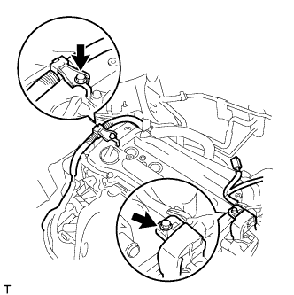
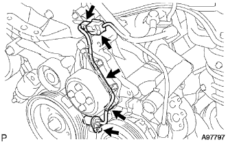
Remove the 2 bolts and disconnect the 2 engine wires.
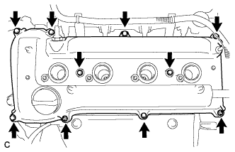
Remove the 8 bolts, 2 nuts, and the cylinder head cover.
19.
SET NO. 1 CYLINDER TO TDC/COMPRESSION
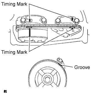
Turn the crankshaft pulley until its groove and the timing mark "0" of the timing chain cover are aligned.
Check that each timing mark of the camshaft timing gear and sprocket is aligned with each timing mark located on the No. 1 and No. 2 bearing caps as shown in the illustration. If not, turn the crankshaft 1 revolution (360°) to align the timing marks as above.
20.
REMOVE CRANKSHAFT PULLEY
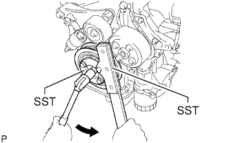
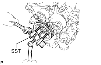
Using SST, hold the pulley in place and loosen the pulley bolt.