2006-2011 Camry Aurion · Service Manual BODY ELECTRICAL

Door Control Switch Circuit

Circuit diagnosis · Vehicles built Oct 2006 – May 2009

Versions by build date: Oct 2006 – May 2009 from Jun 2009

DESCRIPTION

  1. for LHD Driver Side:
    When the lock side of the door control switch is pressed, continuity is established between terminal 2 and terminal 1 of the switch. When the unlock side of the switch is pressed, continuity is established between terminal 9 and 1 of the switch.
    Terminals L1 and UL1 of the main body ECU are connected to the door control switch and door lock/unlock request signals (by door control switch operation) are input to the ECU.
    The main body ECU constantly applies voltage to terminal 2 of the door control switch via terminal L1. When the door control switch is operated to lock all doors, current flows from terminal L1 to terminal 2. The main body ECU determines that this is door lock request signal input.
    The main body ECU also applies constant voltage to terminal 9 of the door control switch via terminal UL1. When the door control switch is operated to unlock the doors, current flows from terminal UL1 to terminal 9. The main body ECU determines that this is door unlock request signal input.
  2. for RHD Driver Side:
    When the lock side of the door control switch is pressed, continuity is established between terminal 2 and terminal 9 of the switch. When the unlock side of the switch is pressed, continuity is established between terminal 8 and 9 of the switch.
    Terminals L1 and UL1 of the main body ECU are connected to the door control switch and door lock/unlock request signals (by door control switch operation) are input to the ECU.
    The main body ECU constantly applies voltage to terminal 2 of the door control switch via terminal L1. When the door control switch is operated to lock all doors, current flows from terminal L1 to terminal 2. The main body ECU determines that this is door lock request signal input.
    The main body ECU also applies constant voltage to terminal 8 of the door control switch via terminal UL1. When the door control switch is operated to unlock the doors, current flows from terminal UL1 to terminal 8. The main body ECU determines that this is door unlock request signal input.
  3. for LHD Passenger Side:
    When the lock side of the door control switch is pressed, continuity is established between terminal 4 and terminal 3 of the switch. When the unlock side of the switch is pressed, continuity is established between terminal 2 and 3 of the switch.
    Terminals L1 and UL1 of the main body ECU are connected to the door control switch and door lock/unlock request signals (by door control switch operation) are input to the ECU.
    The main body ECU constantly applies voltage to terminal 4 of the door control switch via terminal L1. When the door control switch is operated to lock all doors, current flows from terminal L1 to terminal 4. The main body ECU determines that this is door lock request signal input.
    The main body ECU also applies constant voltage to terminal 2 of the door control switch via terminal UL1. When the door control switch is operated to unlock the doors, current flows from terminal UL1 to terminal 2. The main body ECU determines that this is door unlock request signal input.
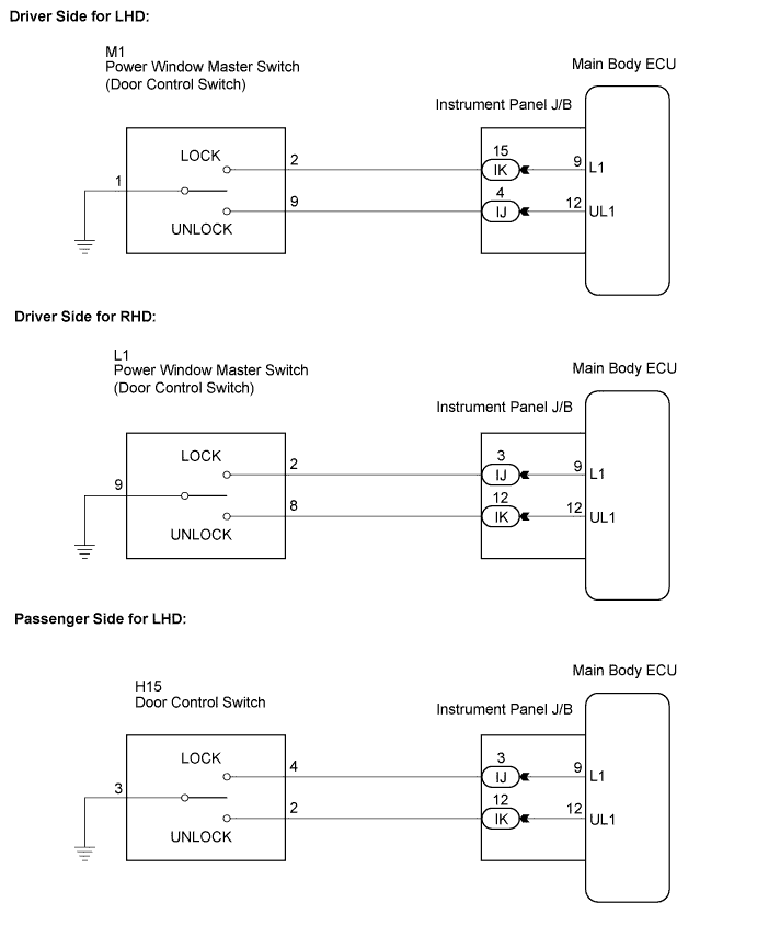
WIRING DIAGRAM

B150924E02

INSPECTION PROCEDURE


1. INSPECT DOOR CONTROL SWITCH

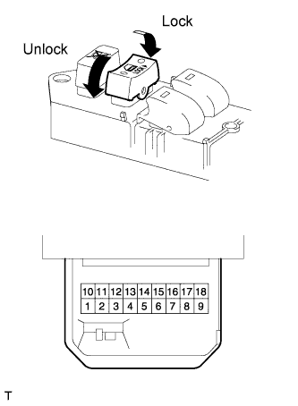
  1. E123893E04
    Inspect the driver's door control switch.
    1. Remove the master switch (Click here).

    2. Measure the resistance between the specified terminals of the door control switch.

      Standard resistance:
      for LHD:
      Tester Connection
      Switch Condition
      Specified Condition
      2 - 1
      Lock
      Below 1 Ω
      2 - 1
      OFF (Free)
      10 kΩ or higher
      9 - 1
      Unlock
      Below 1 Ω
      9 - 1
      OFF (Free)
      10 kΩ or higher
      for RHD:
      Tester Connection
      Switch Condition
      Specified Condition
      2 - 9
      Lock
      Below 1 Ω
      2 - 9
      OFF (Free)
      10 kΩ or higher
      8 - 9
      Unlock
      Below 1 Ω
      8 - 9
      OFF (Free)
      10 kΩ or higher

      Result:
      Result
      Proceed to
      OK
      A
      NG
      B

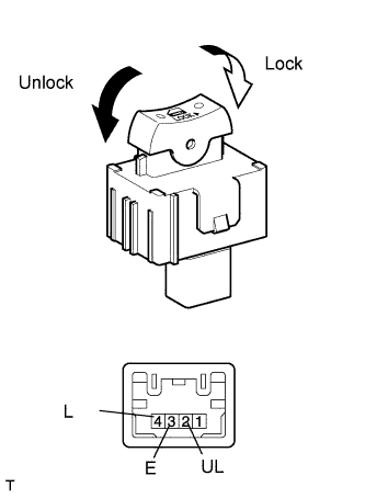
  1. E123894E01
    Inspect the passenger door control switch for LHD.
    1. Remove the door control switch assembly (Click here).

    2. Measure the resistance according to the value(s) in the table below.

      Standard resistance:
      Tester Connection
      Condition
      Specified Condition
      4 - 3
      Lock
      Below 1 Ω
      4 - 3
      2 - 3
      OFF (Free)
      10 kΩ or higher
      2 - 3
      Unlock
      Below 1 Ω

      Result:
      Result
      Proceed to
      OK
      A
      NG
      C


B
REPLACE POWER WINDOW MASTER SWITCH ASSEMBLY (Click here)

C
REPLACE DOOR CONTROL SWITCH ASSEMBLY (Click here)
A


2. CHECK HARNESS AND CONNECTOR (DOOR CONTROL SWITCH - MAIN BODY ECU)

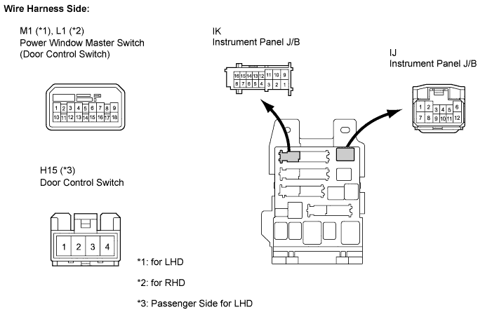
  1. Disconnect the door control switch connector.B150963E01

  1. Disconnect the instrument panel J/B connector.

  1. Measure the resistance according to the value(s) in the table below.

    Standard resistance:
    Driver Side for LHD:
    Tester Connection
    Condition
    Specified Condition
    M1-2 - IK-15
    Always
    Below 1 Ω
    M1-9 - IJ-4
    Always
    Below 1 Ω
    M1-1 - Body ground
    Always
    Below 1 Ω
    IK-15 - Body ground
    Always
    10 kΩ or higher
    IJ-4 - Body ground
    Always
    10 kΩ or higher
    Driver Side for RHD:
    Tester Connection
    Condition
    Specified Condition
    L1-2 - IJ-3
    Always
    Below 1 Ω
    L1-8 - IK-12
    Always
    Below 1 Ω
    L1-9 - Body ground
    Always
    Below 1 Ω
    IJ-3 - Body ground
    Always
    10 kΩ or higher
    IK-12 - Body ground
    Always
    10 kΩ or higher
    Passenger Side for LHD:
    Tester Connection
    Condition
    Specified Condition
    H15-4 - IJ-3
    Always
    Below 1 Ω
    H15-2 - IK-12
    Always
    Below 1 Ω
    H15-3 - Body ground
    Always
    Below 1 Ω
    IJ-3 - Body ground
    Always
    10 kΩ or higher
    IK-12 - Body ground
    Always
    10 kΩ or higher


NG
REPAIR OR REPLACE HARNESS OR CONNECTOR
OK

PROCEED TO NEXT CIRCUIT INSPECTION SHOWN IN PROBLEM SYMPTOMS TABLE (Click here)


← Driver Side Door Key Lock and Unlock Switch Circuit (from Jun 2009)Door Control Switch Circuit (from Jun 2009) →