REMOVAL
Removal / installation · Vehicles built Jun 2006 – Sep 2006
Versions by build date: Jun 2006 – Sep 2006 Oct 2006 – May 2009 from Jun 2009
- HINT:
- Use the same procedures for the RH side and the LH side.
- The procedures listed below are for the LH side.
| 2.
REMOVE FRONT AXLE HUB NUT
|
 |
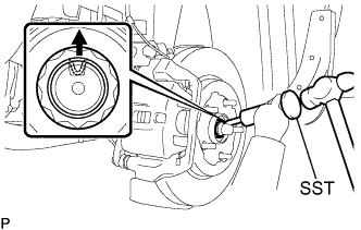
- Using SST and a hammer, release the staked part of the front axle hub nut.
- SST
- 09930-00010
- NOTICE:
- Loosen the staked part of the nut completely, otherwise the thread of the drive shaft may be damaged.
While applying the brakes, remove the front axle hub nut.
| 3.
SEPARATE FRONT SPEED SENSOR
|
|
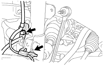
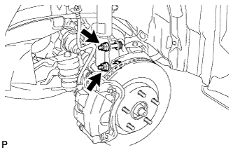
- Remove the bolt and clip, and separate the speed sensor wire and flexible hose from the shock absorber.
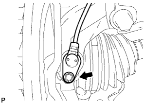
- Remove the bolt and separate the speed sensor from the steering knuckle.
- NOTICE:
- Prevent foreign matter from adhering to the speed sensor.
- Be careful not to damage the speed sensor.
| 4.
SEPARATE FRONT DISC BRAKE CALIPER ASSEMBLY
|
|
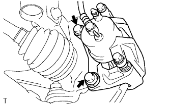
- Remove the 2 bolts and separate the front disc brake caliper assembly from the steering knuckle.
- NOTICE:
- Use wire or an equivalent tool to keep the brake caliper from hanging down by the flexible hose.
| 5.
REMOVE FRONT DISC
|
|
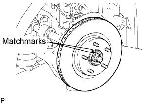
- Remove the front disc.
- HINT:
- Put matchmarks on the disc and the axle hub.
| 6.
SEPARATE TIE ROD END ASSEMBLY
|
|
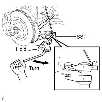
Remove the cotter pin and the nut.
- Using SST, separate the tie rod assembly LH from the steering knuckle.
- SST
- 09628-00011
- NOTICE:
- Hang SST with a string, etc. to prevent it from falling.
- Do not damage the front disc brake dust cover.
- Do not damage the ball joint dust cover.
- Do not damage the steering knuckle.
| 7.
SEPARATE FRONT SUSPENSION LOWER NO. 1 ARM
|
|
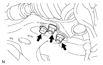
- Remove the bolt and 2 nuts, and separate the front suspension lower No. 1 arm from the lower ball joint.
| 8.
REMOVE FRONT AXLE ASSEMBLY
|
|
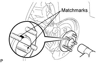
- Put matchmarks on the front drive shaft assembly and the front axle hub sub-assembly.
Using a plastic hammer, separate the front drive shaft assembly from the front axle assembly.
- NOTICE:
- Be careful not to damage the drive shaft boot and speed sensor rotor.
- Remove the 2 bolts, 2 nuts, and front axle assembly.
| 9.
SEPARATE FRONT DISC BRAKE DUST COVER |
|
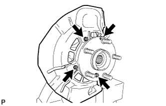
Secure the steering knuckle in a vise using aluminum plates.
- Remove the 4 bolts and separate the front disc brake dust cover from the steering knuckle.
| 10.
REMOVE FRONT LOWER BALL JOINT |
|
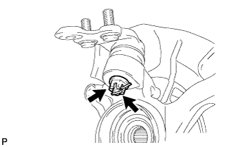
- Remove the cotter pin and nut.
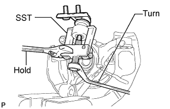
- Using SST, remove the front lower ball joint.
- SST
- 09628-62011
- NOTICE:
- Do not damage the dust cover of the ball joint.
- Do not damage the steering knuckle.