2006-2011 Camry Aurion · Service Manual BODY ELECTRICAL

Rear Door UNLOCK Detection Switch RH Circuit

Circuit diagnosis · Vehicles built Jun 2006 – May 2009

Versions by build date: Jun 2006 – May 2009 from Jun 2009

DESCRIPTION

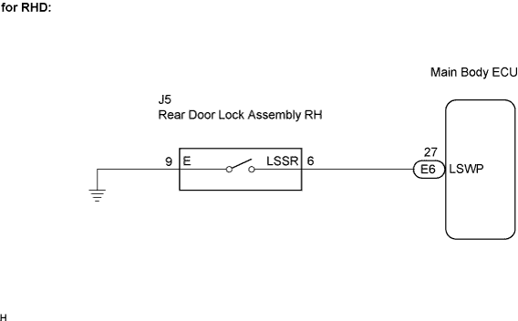
The rear right door unlock detection switch is built into the rear right side door lock assembly. The switch turns on when the rear right door is unlocked and turns off when the door is locked.
The main body ECU is connected to the rear right door lock assembly via terminal LSWP and rear right door lock/unlock state signals are input to the ECU.
The main body ECU applies voltage to the door unlock detection switch via terminal LSWP. When the door unlock detection switch is on (there is continuity between the switch terminals), an unlock state signal is input to the ECU. When the switch is off (there is no continuity between the switch terminals), a lock state signal is input.

WIRING DIAGRAM

B109773E51

INSPECTION PROCEDURE


1. INSPECT REAR DOOR LOCK ASSEMBLY (UNLOCK DETECTION SWITCH)

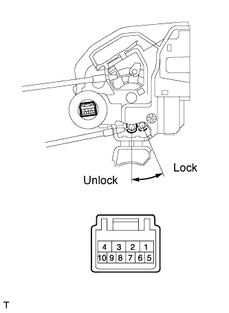
  1. E123891E02
    Remove the rear door lock assembly RH.

  1. Measure the resistance according to the value(s) in the table below.
    Standard resistance:
    Tester Connection
    Measurement Condition
    Door Lock Condition
    Specified Condition
    6 - 9
    Battery positive (+) → Terminal 4
    Battery negative (-) → Terminal 1
    Lock
    10 kΩ or higher
    6 - 9
    Battery positive (+) → Terminal 1
    Battery negative (-) → Terminal 4
    Unlock
    Below 1 Ω


NG
REPLACE REAR DOOR LOCK ASSEMBLY
OK


2. CHECK WIRE HARNESS (REAR DOOR LOCK - MAIN BODY ECU (INSTRUMENT PANEL J/B))

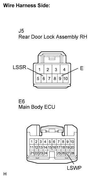
  1. B111708E15
    Disconnect the rear door lock assembly RH connector.

  1. Disconnect the ECU connector.

  1. Measure the resistance according to the value(s) in the table below.

    Standard resistance:
    Tester Connection (Symbols)
    Condition
    Specified Condition
    J5-6 (LSSR) - E6-27 (LSWP)
    Always
    Below 1 Ω
    J5-6 (LSSR) - Body ground
    Always
    10 kΩ or higher
    J5-9 (E) - Body ground
    Always
    Below 1 Ω


NG
REPAIR OR REPLACE HARNESS OR CONNECTOR
OK

PROCEED TO NEXT CIRCUIT INSPECTION SHOWN IN PROBLEM SYMPTOMS TABLE


← Rear Door UNLOCK Detection Switch LH Circuit (from Jun 2009)Rear Door UNLOCK Detection Switch RH Circuit (from Jun 2009) →