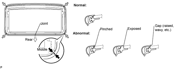
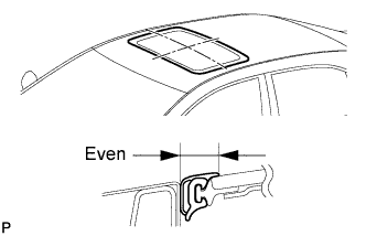
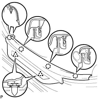
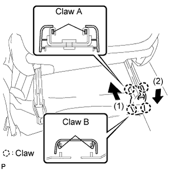
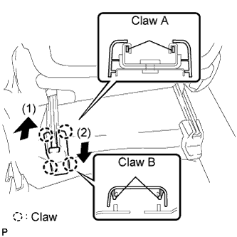
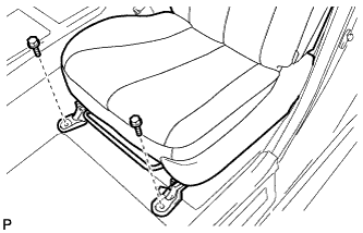
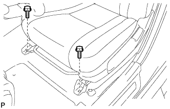
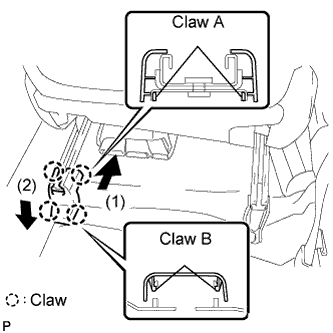
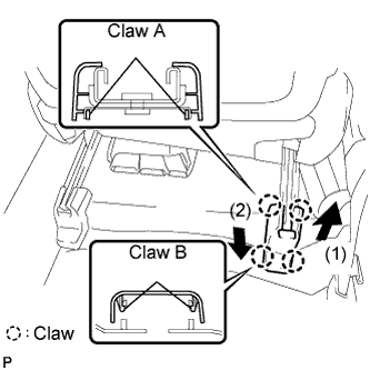
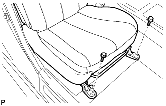
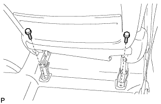
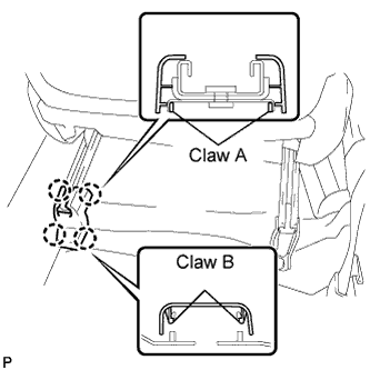
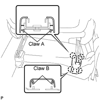
Position the joint of the weatherstrip at the rear center.
Align the marks on the weatherstrip with the middle marks at the corners of the sliding roof panel and install the weatherstrip.
Install the lip of the weatherstrip firmly.
2.
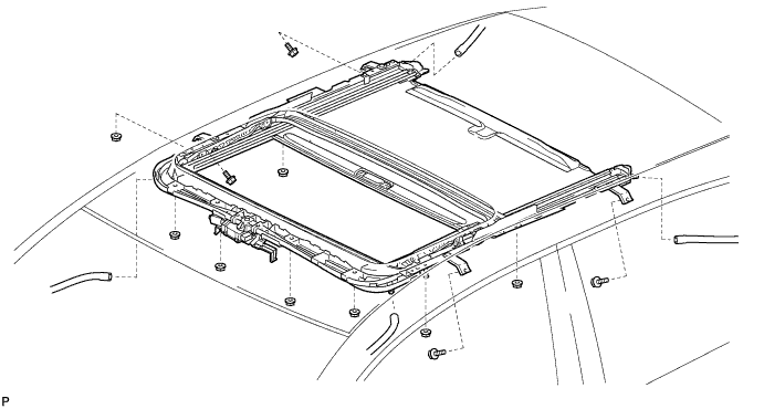
INSTALL SLIDING ROOF HOUSING SUB-ASSEMBLY
Install the sliding roof housing sub-assembly with the 4 bolts and 8 nuts.
Torque:
5.5 N*m{
56 kgf*cm
, 49 in.*lbf
}
Connect the 4 sliding roof drain hoses.
3.
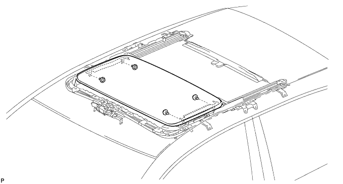
INSTALL SLIDING ROOF GLASS SUB-ASSEMBLY
Using a T25 "TORX" driver, temporarily install the sliding roof glass sub-assembly with the 4 screws.
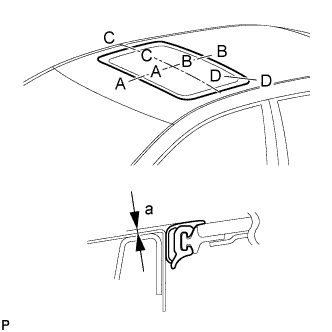
Perform a level check.
Check the difference in level "a", between the roof panel and the upper surface of the weatherstrip, when the sliding roof glass is fully closed.
Standard:
Area
Measurement
A - A
0 + 1.0 mm (0 + 0.039 in.) 0 - 2.0 mm (0 - 0.079 in.)
B - B
0 + 2.0 mm (0 + 0.079 in.) 0 - 1.0 mm (0 - 0.039 in.)
C - C
0 + 1.5 mm (0 + 0.059 in.) 0 - 1.5 mm (0 - 0.059 in.)
D - D
0 + 1.5 mm (0 + 0.059 in.) 0 - 1.0 mm (0 - 0.039 in.)
HINT:
"+" represents the condition that the glass is above the panel level. "-" represents the condition that the glass is below the panel level.
Perform a gap check.
Check the gap between the roof panel and roof glass.
NOTICE:
The gap must be even all around.
After adjusting the sliding roof glass, using a T25 "TORX" driver, install the sliding roof glass sub-assembly with the 4 screws.
Torque:
4.0 N*m{
41 kgf*cm
, 35 in.*lbf
}
4.
INSPECT FOR WATER LEAK
After adjusting the sliding roof glass sub-assembly, check for water leaks.
If there are any leaks, readjust the sliding roof glass sub-assembly.
5.
INSTALL SLIDING ROOF SIDE GARNISH LH
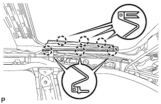
Engage the 6 claws and install the sliding roof side garnish LH.
6.
INSTALL SLIDING ROOF SIDE GARNISH RH
HINT:
Use the same procedure for the RH side and the LH side.
7.
INSTALL CURTAIN SHIELD AIRBAG ASSEMBLY LH
Check that the ignition switch is off.
Check that the battery negative (-) cable is disconnected.
CAUTION:
Wait for 90 seconds after disconnecting the cable to prevent airbag deployment.
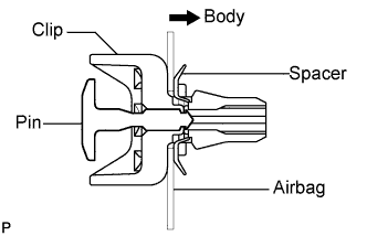
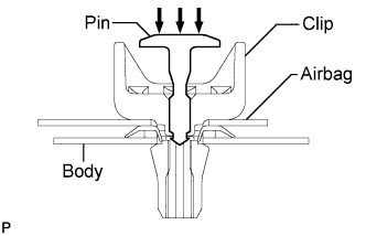
Install 4 new clips and 4 new spacers to the curtain shield airbag assembly as shown in the illustration.
NOTICE:
Do not push in the pin.
Make sure that the clips are installed in the correct direction.
Make sure that the spacers are installed properly, in the correct direction, and that they are not damaged.
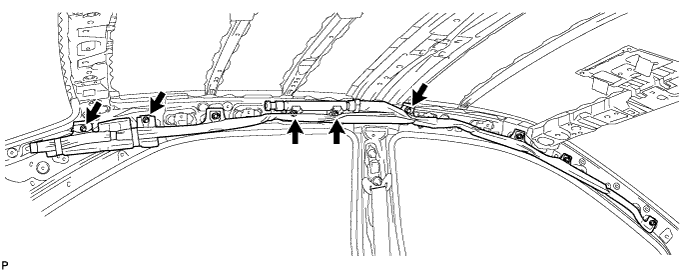
Install the curtain shield airbag assembly with 5 new bolts.
Torque:
11 N*m{
112 kgf*cm
, 8 ft.*lbf
}
NOTICE:
Do not twist the curtain shield airbag assembly when installing it.
Install the 4 clips with the curtain shield airbag assembly to the body panel as shown in the illustration.
NOTICE:
Make sure that the pins of the clips are pushed in firmly.
Mark the clips.
HINT:
Mark the clips to make sure that they are not reused.
Connect the connector.
NOTICE:
When handling the airbag connector, take care not to damage the airbag wire harness.
8.
INSTALL CURTAIN SHIELD AIRBAG ASSEMBLY RH
HINT:
Use the same procedure for the RH side and the LH side.
9.
INSTALL ROOF HEADLINING ASSEMBLY
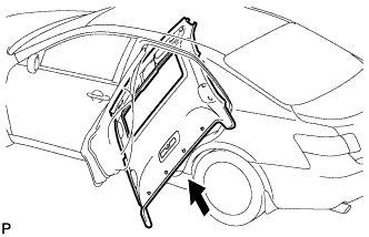
Pull the roof headlining assembly into the vehicle through the rear left door.
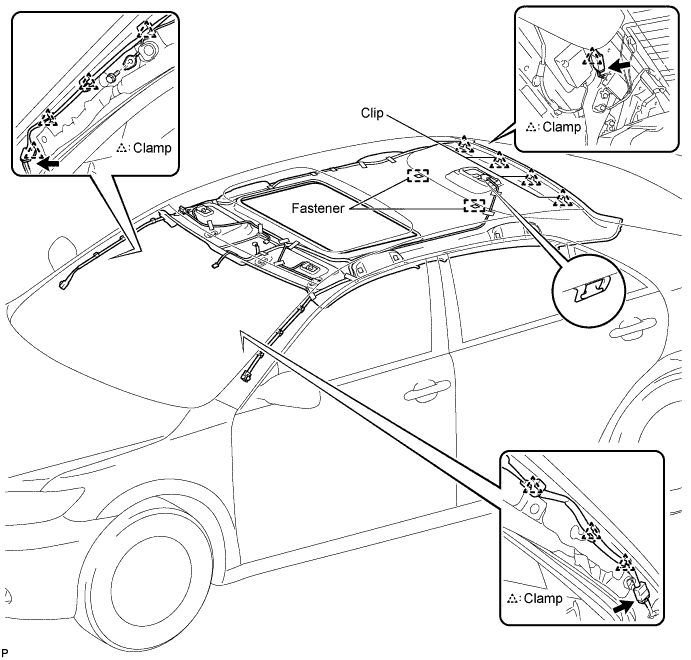
Engage the hook, 4 clips, and 2 fasteners.
Connect the sliding roof drive gear connector.
Connect the antenna cord sub-assembly connector and engage the clamp to the rear pillar RH.
Connect the antenna cord sub-assembly connector and engage each clamp to the front pillar RH.
Install the radio setting condenser to the front pillar RH with the bolt.
Connect the No. 1 roof wire connector and engage each clamp to the front pillar LH.
10.
INSTALL SUN ROOF OPENING TRIM MOULDING
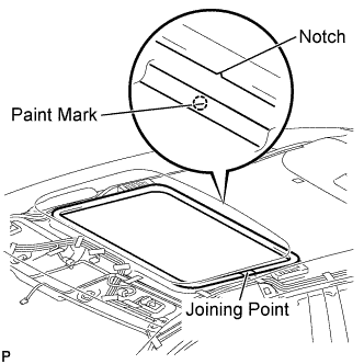
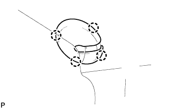
Align the paint mark on the inner surface of the opening trim moulding with the notch of the roof headlining, and install the sun roof opening trim moulding so that the joining point of the opening trim is on the left side of the vehicle as shown in the illustration.
NOTICE:
After installation, check that the corners fit correctly.
11.
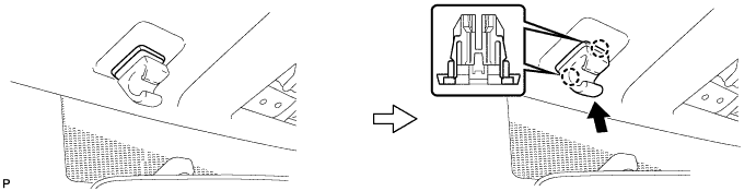
INSTALL SPOT LIGHT ASSEMBLY
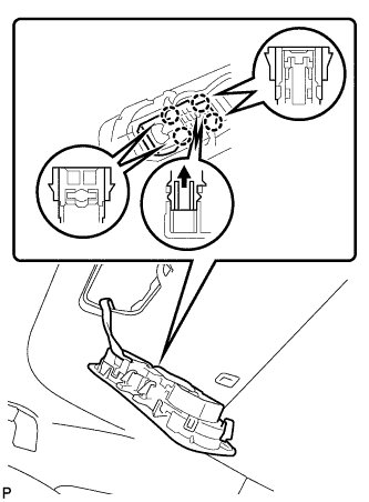
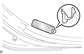
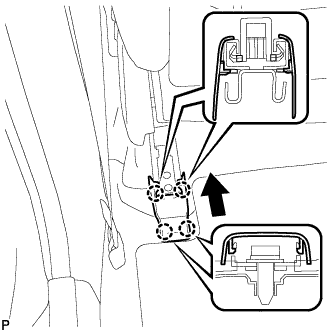
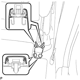
Push the light bulb holder in the direction indicated by the arrow in the illustration to engage the claw.
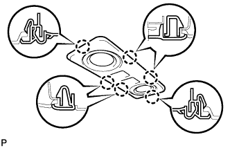
Engage the 4 claws.
Engage the 6 claws and install the spot light assembly.
12.
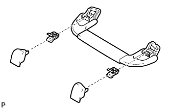
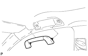
INSTALL FRONT ASSIST GRIP SUB-ASSEMBLY (for Driver Side)
with Assist Grip:
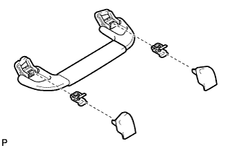
Assemble the front assist grip sub-assembly as shown in the illustration.
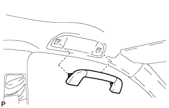
Install the front assist grip sub-assembly.
13.
INSTALL FRONT ASSIST GRIP SUB-ASSEMBLY (for Front Passenger Side)
Assemble the front assist grip sub-assembly as shown in the illustration.
Install the front assist grip sub-assembly.
14.
INSTALL REAR ASSIST GRIP SUB-ASSEMBLY
HINT:
Use the same procedure for the rear side and front side.
15.
INSTALL VISOR HOLDER
Engage the 2 claws.
Push in the visor holder as shown in the illustration.
HINT:
Use the same procedure for the RH side and the LH side.
16.
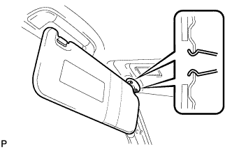
INSTALL VISOR ASSEMBLY LH
Engage the 2 clips and install the visor assembly LH.
Engage the 4 claws and install the visor bracket cover.
17.
INSTALL VISOR ASSEMBLY RH
HINT:
Use the same procedure for the RH side and LH side.
18.
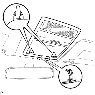
INSTALL ROOF CONSOLE BOX ASSEMBLY
Connect the connectors.
Engage the 2 claws and 2 clips, and then install the roof console box assembly.
19.
INSTALL RAIN SENSOR COVER (w/ Rain Sensor)
Install the rain sensor cover.
20.
INSTALL FRONT PILLAR GARNISH LH (w/o Curtain Shield Airbag)
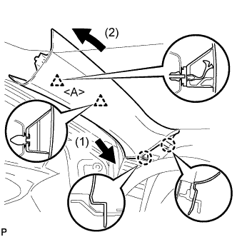
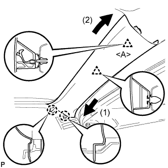
Install a new clip <A> on the front pillar garnish LH.
Engage the 2 claws and 2 clips, then install the front pillar garnish LH.
21.
INSTALL FRONT PILLAR GARNISH LH (w/ Curtain Shield Airbag)
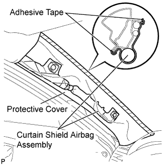
Remove the protective cover.
Install a new clip <A> on the front pillar garnish LH.
Engage the 2 claws and 2 clips, then install the front pillar garnish LH.
22.
INSTALL FRONT PILLAR GARNISH RH (w/o Curtain Shield Airbag)
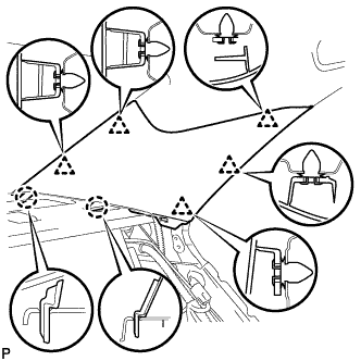
Install a new clip <A> on the front pillar garnish RH.
Engage the 2 claws and 2 clips, then install the front pillar garnish RH.
23.
INSTALL FRONT PILLAR GARNISH RH (w/ Curtain Shield Airbag)
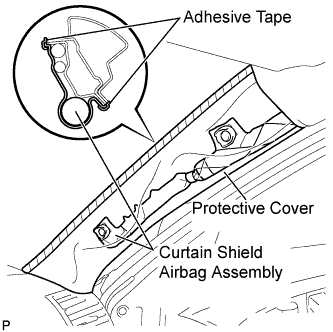
Remove the protective cover.
Install a new clip <A> on the front pillar garnish RH.
Engage the 2 claws and 2 clips, then install the front pillar garnish RH.
24.
INSTALL ROOF SIDE INNER GARNISH LH
Engage the 5 clips and 2 claws, then install the roof side inner garnish LH.
25.
INSTALL ROOF SIDE INNER GARNISH RH
HINT:
Use the same procedure for the RH side and LH side.
26.
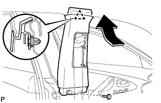
INSTALL UPPER CENTER PILLAR GARNISH LH
Engage the clip.
Install the upper center pillar garnish LH with the bolt.
27.
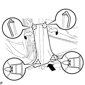
INSTALL LOWER CENTER PILLAR GARNISH LH
Engage the 2 claws and 2 clips, then install the lower center pillar garnish LH.
28.
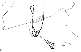
CONNECT FRONT SEAT OUTER BELT ASSEMBLY LH
Install the floor end of the front seat outer belt assembly LH with the bolt.
Torque:
42 N*m{
428 kgf*cm
, 31 ft.*lbf
}
29.
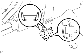
INSTALL LAP BELT OUTER ANCHOR COVER (for LH Side)
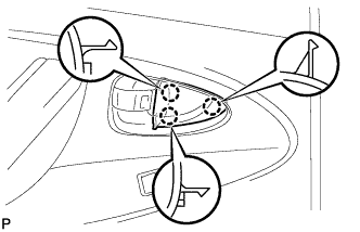
Engage the 3 claws and install the lap belt outer anchor cover.
30.
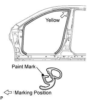
INSTALL FRONT DOOR OPENING TRIM WEATHERSTRIP LH
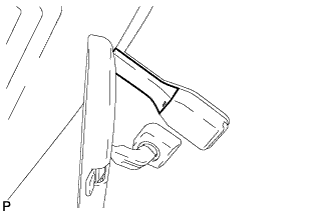
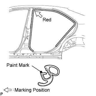
Install the front door opening trim weatherstrip LH as shown in the illustration.
NOTICE:
After installation, check that the corners fit correctly.
31.
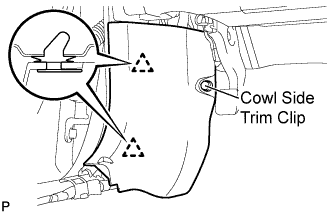
INSTALL COWL SIDE TRIM SUB-ASSEMBLY LH
Engage the 2 clips.
Install the cowl side trim sub-assembly LH with the cowl side trim clip.
32.
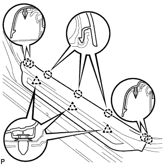
INSTALL FRONT DOOR SCUFF PLATE LH
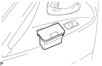
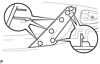
Engage the 7 claws and 3 clips, then install the front door scuff plate LH.
33.
INSTALL UPPER CENTER PILLAR GARNISH RH
HINT:
Use the same procedure for the RH side and LH side.
34.
INSTALL LOWER CENTER PILLAR GARNISH RH
HINT:
Use the same procedure for the RH side and LH side.
35.
CONNECT FRONT SEAT OUTER BELT ASSEMBLY RH
HINT:
Use the same procedure for the RH side and LH side.
36.
INSTALL LAP BELT OUTER ANCHOR COVER (for RH Side)
HINT:
Use the same procedure for the RH side and LH side.
37.
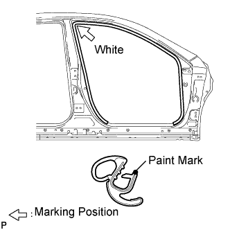
INSTALL FRONT DOOR OPENING TRIM WEATHERSTRIP RH
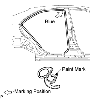
Install the front door opening trim weatherstrip RH as shown in the illustration.
NOTICE:
After installation, check that the corners fit correctly.
38.
INSTALL COWL SIDE TRIM SUB-ASSEMBLY RH
HINT:
Use the same procedure for the RH side and LH side.
39.
INSTALL FRONT DOOR SCUFF PLATE RH
HINT:
Use the same procedure for the RH side and LH side.
40.
INSTALL REAR DOOR INNER GLASS WEATHERSTRIP LH
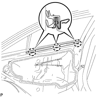
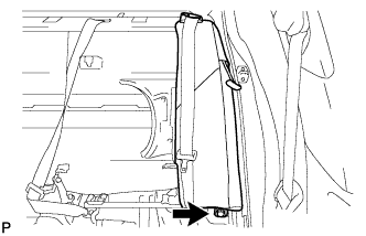
Engage the 3 claws to install the rear door inner glass weatherstrip.
41.
INSTALL REAR DOOR TRIM BOARD SUB-ASSEMBLY LH
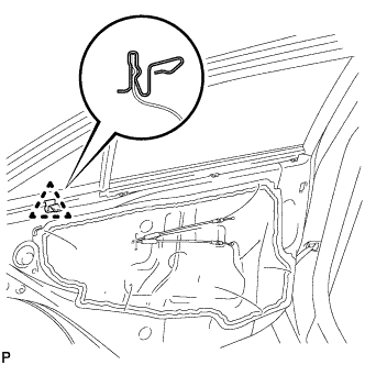
Engage the claw to install the No. 1 door scuff plate clamp.
Connect each connector.
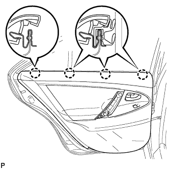
Engage the rear door trim board with the 4 clips of the rear door inner glass weatherstrip.
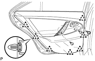
Engage the 7 clips to install the rear door trim board to the rear door panel.