Home › BODY ELECTRICAL › DOOR LOCK › SMART ENTRY AND START SYSTEMEntry Lock Switch Circuit
Circuit diagnosis · Vehicles built Oct 2006 – May 2009
Versions by build date: Oct 2006 – May 2009 from Jun 2009
DESCRIPTION
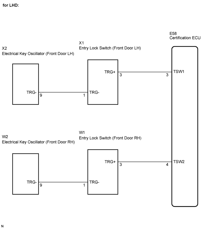
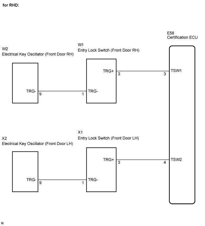
The entry lock switch (trigger switch) is built into the outside handle of the driver door and passenger door. The certification ECU detects the conditions of the lock switch. WIRING DIAGRAM
INSPECTION PROCEDURE
1. INSPECT ENTRY LOCK SWITCH
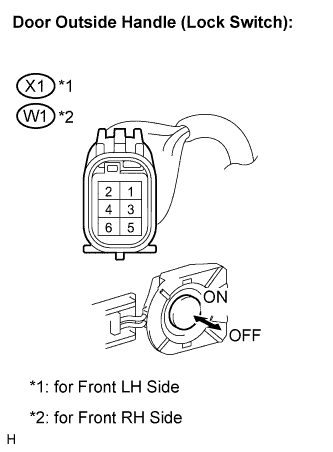
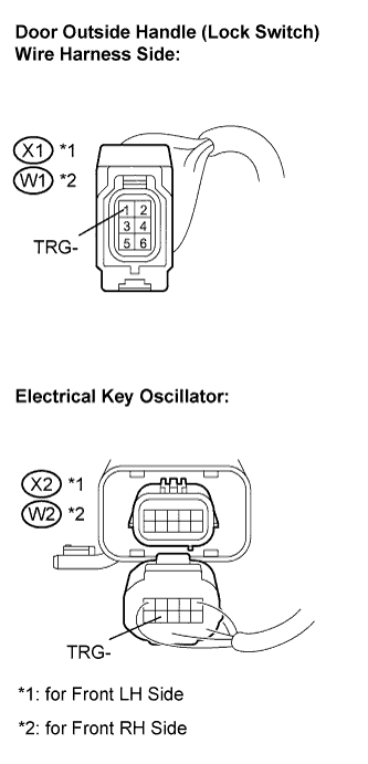
Remove the outside handle. Disconnect the connectors.
Measure the resistance according to the value(s) in the table below.
Standard resistance:
for Front LH Side:
Tester Connection (Symbols)
Condition
Specified Condition
X1-1 (TRG-) - X1-3 (TRG+)
Lock switch not pushed
10 kΩ or higher
Lock switch pushed
Below 1 Ω
for Front RH Side:
Tester Connection (Symbols)
Condition
Specified Condition
W1-1 (TRG-) - W1-3 (TRG+)
Lock switch not pushed
10 kΩ or higher
Lock switch pushed
Below 1 Ω
NG
REPLACE OUTSIDE HANDLE ASSEMBLY
OK
2. CHECK HARNESS AND CONNECTOR (CERTIFICATION ECU - ENTRY LOCK SWITCH)
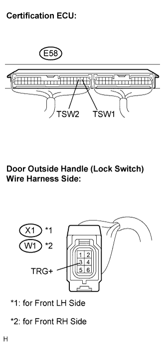
Disconnect the E58 ECU connector. Measure the resistance according to the value(s) in the table below.
Standard resistance:
for LHD (Front LH Side):
Tester Connection (Symbols)
Condition
Specified Condition
E58-3 (TSW1) - X1-3 (TRG+)
Always
Below 1 Ω
E58-3 (TSW1) - Body ground
Always
10 kΩ or higher
for LHD (Front RH Side):
Tester Connection (Symbols)
Condition
Specified Condition
E58-4 (TSW2) - W1-3 (TRG+)
Always
Below 1 Ω
E58-4 (TSW2) - Body ground
Always
10 kΩ or higher
for RHD (Front RH Side):
Tester Connection (Symbols)
Condition
Specified Condition
E58-3 (TSW1) - W1-3 (TRG+)
Always
Below 1 Ω
E58-3 (TSW1) - Body ground
Always
10 kΩ or higher
for RHD (Front LH Side):
Tester Connection (Symbols)
Condition
Specified Condition
E58-4 (TSW2) - X1-3 (TRG+)
Always
Below 1 Ω
E58-4 (TSW2) - Body ground
Always
10 kΩ or higher
NG
REPAIR OR REPLACE HARNESS OR CONNECTOR
OK
3. CHECK HARNESS AND CONNECTOR (ELECTRICAL KEY OSCILLATOR - ENTRY LOCK SWITCH)
Disconnect the door oscillator connector. Measure the resistance according to the value(s) in the table below.
Standard resistance:
for Front LH Side:
Tester Connection (Symbols)
Condition
Specified Condition
X2-9 (TRG-) - X1-1 (TRG-)
Always
Below 1 Ω
X2-9 (TRG-) - Body ground
Always
10 kΩ or higher
for Front RH Side:
Tester Connection (Symbols)
Condition
Specified Condition
W2-9 (TRG-) - W1-1 (TRG-)
Always
Below 1 Ω
W2-9 (TRG-) - Body ground
Always
10 kΩ or higher
NG
REPAIR OR REPLACE HARNESS OR CONNECTOR
OK
4. CHECK AND REPLACE ELECTRICAL KEY OSCILLATOR
Replace the electrical key oscillator.
Check that the entry LOCK/UNLOCK function operates normally.
OK:
Entry LOCK/UNLOCK function operates normally.
NG
PROCEED TO NEXT CIRCUIT INSPECTION SHOWN IN PROBLEM SYMPTOMS TABLE (Click here )
OK
END (ELECTRICAL KEY OSCILLATOR IS DEFECTIVE)