REMOVAL
Removal / installation · Vehicles built Jun 2006 – Sep 2006
Versions by build date: Jun 2006 – Sep 2006 Oct 2006 – May 2009 from Jun 2009
| 1.
PLACE FRONT WHEELS FACING STRAIGHT AHEAD |
|
| 2.
DISCONNECT CABLE FROM NEGATIVE BATTERY TERMINAL |
|
| 4.
SEPARATE STEERING INTERMEDIATE SHAFT ASSEMBLY |
 |
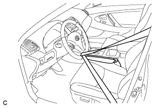
- Secure the steering wheel with the seat belt in order to prevent rotation.
- HINT:
- This operation is useful to prevent damage to the spiral cable.
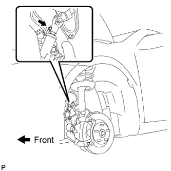
- Remove the bolt and slide the steering intermediate shaft assembly.
- NOTICE:
- Do not separate the steering intermediate shaft assembly from the power steering link assembly.
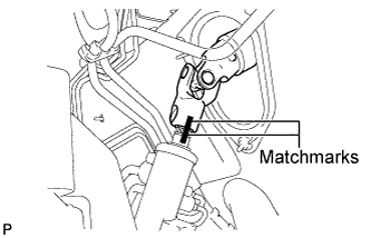
- Put matchmarks on the steering intermediate shaft assembly and the power steering link assembly.
Separate the steering intermediate shaft assembly from the power steering link assembly.
| 5.
SEPARATE TIE ROD ASSEMBLY LH |
|
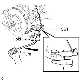
Remove the cotter pin and the nut.
- Using SST, separate the tie rod assembly LH from the steering knuckle.
- SST
- 09628-00011
- NOTICE:
- Hang SST with a string, etc. to prevent it from falling.
- Do not damage the front disc brake dust cover.
- Do not damage the ball joint dust cover.
- Do not damage the steering knuckle.
| 6.
SEPARATE TIE ROD ASSEMBLY RH |
|
- HINT:
- Perform the same procedure as for the LH side.
| 7.
REMOVE ENGINE ASSEMBLY WITH TRANSAXLE |
|
- HINT:
- Refer to the instructions for removal of the engine assembly (Click here).
| 8.
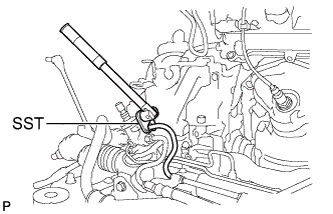
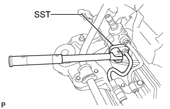
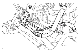
DISCONNECT PRESSURE FEED TUBE ASSEMBLY (for LHD) |
|
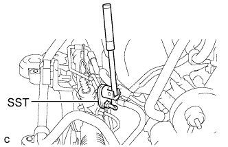
- Using SST, disconnect the pressure feed tube assembly (return tube side) from the power steering link assembly.
- SST
- 09023-12701
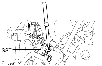
- Using SST, disconnect the pressure feed tube assembly (pressure feed tube side) from the power steering link assembly.
- SST
- 09023-12701
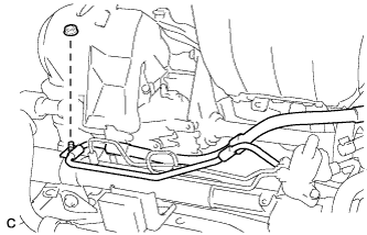
- Remove the 2 bolts and separate the pressure feed tube clamp.
| 9.
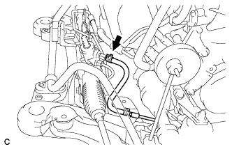
DISCONNECT RETURN TUBE SUB-ASSEMBLY (for RHD) |
|
- Slide the clip and disconnect the outlet return tube sub-assembly.
| 10.
REMOVE RETURN TUBE ASSEMBLY (for RHD) |
|
- Using SST, remove the return tube assembly from the power steering link assembly.
- SST
- 09023-12701
| 11.
DISCONNECT PRESSURE FEED TUBE ASSEMBLY (for RHD) |
|
- Using SST, disconnect the pressure feed tube assembly from the power steering link assembly.
- SST
- 09023-12701
- Remove the nut and separate the pressure feed tube clamp.
| 12.
REMOVE POWER STEERING LINK ASSEMBLY |
|
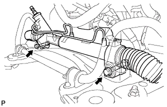
- Remove the 2 bolts, 2 nuts, and power steering link assembly.
- NOTICE:
- Because the nut has its own stopper, do not turn the nut. Loosen the bolt with the nut fixed.
| 13.
REMOVE TIE ROD ASSEMBLY LH |
|
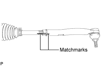
- Put matchmarks on the tie rod assembly LH and the steering rack end sub-assembly.
Loosen the lock nut, and remove the tie rod assembly LH and the lock nut.
| 14.
REMOVE TIE ROD ASSEMBLY RH |
|
- HINT:
- Perform the same procedure as for the LH side.