Interior Light Circuit
Circuit diagnosis · Vehicles built Jun 2006 – May 2009
Versions by build date: Jun 2006 – May 2009 from Jun 2009
DESCRIPTION
The main body ECU controls the illuminated entry system (interior light and ignition key cylinder light).WIRING DIAGRAM
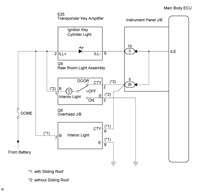

INSPECTION PROCEDURE
| 1. PERFORM ACTIVE TEST USING INTELLIGENT TESTER |
 |
Connect the intelligent tester to the DLC3.
Turn the ignition switch to the ON position and turn the intelligent tester main switch on.
Select the item(s) below in the ACTIVE TEST, and check the operation.
Main Body (Main Body ECU):
Tester Display
|
Test Part
|
Control Range
|
Diagnostic Note
|
Illuminated Entry System
|
Interior light and ignition key cylinder light (Interior light switch is in DOOR position and all doors are closed).
|
ON / OFF
|
-
|
- OK:
- Each light illuminates.
|
OK |
 |
|
| PROCEED TO NEXT CIRCUIT INSPECTION SHOWN IN PROBLEM SYMPTOMS TABLE |
|
|
| NG |
|
 |
|
| 2. CHECK VEHICLE CONDITION |
|
Check the vehicle condition.
- Result:
Condition
|
Proceed to
|
without Sliding Roof
|
A
|
with Sliding Roof
|
B
|
|
B |
 |
|
|
|
| A |
|
|
|
| 3. CHECK HARNESS AND CONNECTOR (LIGHT - BATTERY AND INSTRUMENT PANEL J/B ASSEMBLY) |
|
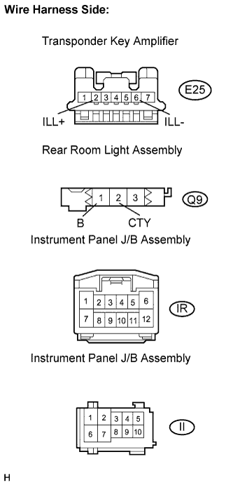
- Disconnect the E25 transponder key amplifier connector.
Disconnect the Q9 rear room light assembly connector.
Disconnect the IR and II instrument panel J/B assembly connectors.
Measure the voltage and resistance according to the value(s) in the table below.
- Standard voltage:
Tester Connection
|
Condition
|
Specified Condition
|
E25-2 (ILL+) - Body ground
|
Always
|
10 to 14 V
|
Q9-1 (B) - Body ground
|
Always
|
10 to 14 V
|
- Standard resistance:
Tester Connection
|
Condition
|
Specified Condition
|
II-10 - E25-6 (ILL-)
|
Always
|
Below 1 Ω
|
IR-5 - Q9-2 (CTY)
|
Always
|
Below 1 Ω
|
II-10 - Body ground
|
Always
|
10 kΩ or higher
|
IR-5 - Body ground
|
Always
|
10 kΩ or higher
|
|
NG |
|
|
| REPAIR OR REPLACE HARNESS OR CONNECTOR |
|
|
| OK |
|
 |
|
| REPLACE INSTRUMENT PANEL JUNCTION BLOCK ASSEMBLY |
|
| 4. CHECK HARNESS AND CONNECTOR (LIGHT - BATTERY AND INSTRUMENT PANEL J/B ASSEMBLY) |
|
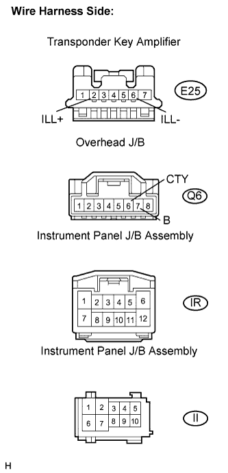
- Disconnect the E25 transponder key amplifier connector.
Disconnect the Q6 overhead J/B connector.
Disconnect the IR and II instrument panel J/B assembly connectors.
Measure the voltage and resistance according to the value(s) in the table below.
- Standard voltage:
Tester Connection
|
Condition
|
Specified Condition
|
E25-2 (ILL+) - Body ground
|
Always
|
10 to 14 V
|
Q6-7 (B) - Body ground
|
Always
|
10 to 14 V
|
- Standard resistance:
Tester Connection
|
Condition
|
Specified Condition
|
II-10 - E25-6 (ILL-)
|
Always
|
Below 1 Ω
|
IR-5 - Q6-6 (CTY)
|
Always
|
Below 1 Ω
|
II-10 - Body ground
|
Always
|
10 kΩ or higher
|
IR-5 - Body ground
|
Always
|
10 kΩ or higher
|
|
NG |
|
|
| REPAIR OR REPLACE HARNESS OR CONNECTOR |
|
|
| OK |
|
|
|
| REPLACE INSTRUMENT PANEL JUNCTION BLOCK ASSEMBLY |
|