Washer Motor Circuit
Circuit diagnosis · Vehicles built from Jun 2006
DESCRIPTION
The windshield wiper relay assembly (auto wiper relay) controls the front washer motor.WIRING DIAGRAM
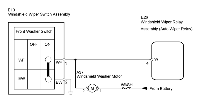

INSPECTION PROCEDURE
| 1. INSPECT FUSE (WASH) |

Remove the WASH fuse from the instrument panel J/B.
Measure the resistance of the fuse.
- Standard resistance:
- Below 1 Ω
|
|
||||

| OK | |
 |
| 2. INSPECT WINDSHIELD WIPER SWITCH ASSEMBLY (WASHER SWITCH) |
Remove the windshield wiper switch assembly.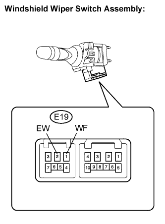
Measure the resistance according to the value(s) in the table below.
- Standard resistance:
Tester Connection
Switch Condition
Specified Condition
E19-1 (WF) - E19-2 (EW)
ON
Below 1 Ω
OFF
10 kΩ or higher
|
|
||||
| OK | |
|
| 3. INSPECT WINDSHIELD WASHER MOTOR AND PUMP ASSEMBLY |
Remove the washer jar.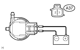
Apply battery voltage to the windshield washer motor connector and check the operation of the windshield washer motor assembly.
- OK:
Measurement Condition
Specified Condition
Battery positive (+) → Terminal A37-1
Battery negative (-) → Terminal A37-2
Washer fluid flows from washer jar
- HINT:
- The check should be performed with the windshield washer motor and pump installed to the washer jar.
|
|
||||
| OK | |
|
| 4. CHECK HARNESS AND CONNECTOR (BATTERY - WASHER MOTOR) |
Measure the voltage according to the value(s) in the table below.
- Standard voltage:
Tester connection
Condition
Specified condition
A37-1 - Body ground
Ignition switch ON
10 to 14 V
|
|
||||
| OK | |
|
| 5. CHECK HARNESS AND CONNECTOR (WASHER MOTOR - WIPER RELAY, WASHER SWITCH) |
Disconnect the E26 windshield wiper relay assembly (auto wiper relay) connector.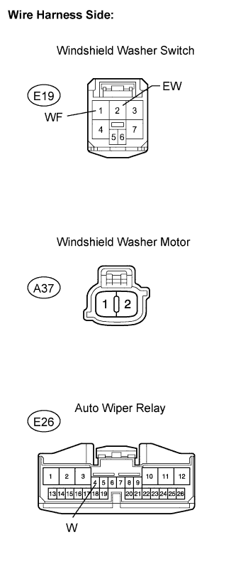
Measure the resistance according to the value(s) in the table below.
- Standard resistance:
Tester Connection
Condition
Specified Condition
A37-2 - E26-4 (W)
Always
Below 1 Ω
A37-2 - E19-1 (WF)
Always
Below 1 Ω
E19-2 (EW) - Body ground
Always
Below 1 Ω
|
|
||||
| OK | ||
 |
||
| ||