Home › BODY › WINDSHIELD / WINDOWGLASS › WINDOW DEFOGGER SYSTEMRear Window Defogger System does not Operate
Circuit diagnosis · Vehicles built Oct 2006 – May 2009
Versions by build date: Jun 2006 – Sep 2006 Oct 2006 – May 2009 from Jun 2009
DESCRIPTION
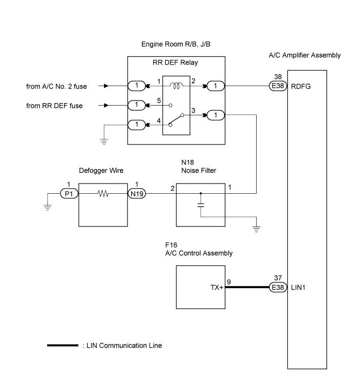
When the rear window defogger switch, which is built into the heater control assembly, is operated, the operation signals are transmitted to the A/C amplifier assembly through LIN. When the A/C amplifier assembly receives the signals, it turns on the DEFOG relay to operate the rear window defogger. WIRING DIAGRAM
INSPECTION PROCEDURE
1. PERFORM ACTIVE TEST USING INTELLIGENT TESTER
Select the ACTIVE TEST, use the intelligent tester to issue a control command, and then check the window defogger operation.
Air Conditioner:
Item
Test Details
Defogger Relay (Rear)
Turns rear window defogger OFF/ON
Result:
Result
Proceed to
The window defogger system does not operate normally when operating it through the intelligent tester.
A
The window defogger system operates normally when operating it through the intelligent tester.
B
A
B
2. CHECK HARNESS AND CONNECTOR (LIN COMMUNICATION LINE)
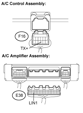
Disconnect the A/C control assembly connector. Measure the resistance according to the value(s) in the table below.
Standard resistance:
Tester Connection
Condition
Specified Condition
E38-37 (LIN1) - F16-9 (TX+)
Always
Below 1 Ω
E38-37 (LIN1) - Body ground
Always
10 kΩ or higher
NG
REPAIR OR REPLACE HARNESS OR CONNECTOR
OK
3. REPLACE AIR CONDITIONER CONTROL ASSEMBLY
Replace the air conditioner control assembly (Click here for Automatic Air Conditioning System, Click here for Manual Air Conditioning System).
NEXT
4. CONFIRM REAR WINDOW DEFOGGER OPERATION
Turn the ignition switch on (IG), press the defogger switch, and check that the window defogger operates.
OK:
Window defogger system operates normally
NG
REPLACE A/C AMPLIFIER ASSEMBLY
OK
5. PERFORM ACTIVE TEST USING INTELLIGENT TESTER
Select the ACTIVE TEST, use the intelligent tester to issue a control command, and then check the DEFOG relay operation.
Air Conditioner:
Item
Test Details
Defogger Relay (Rear)
Turns rear window defogger OFF/ON
Check that operation sound of the RR DEF relay is heard.
Result:
Result
Proceed to
Relay operating sound is heard
A (OK)
Relay operating sound is not heard
B (NG)
A
B
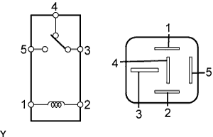
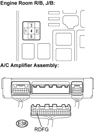
6. INSPECT RR DEF RELAY
Disconnect the RR DEF relay.
Measure the resistance according to the value(s) in the table below.
Standard resistance:
Tester Condition
Specified Condition
3 - 4
Below 1 Ω
3 - 5
10 kΩ or higher
3 - 5
Below 1 Ω
NG
OK
7. CHECK HARNESS AND CONNECTOR (RR DEF RELAY - BATTERY POSITIVE)
Measure the voltage according to the value(s) in the table below.
Standard voltage:
Tester Connection
Condition
Specified Condition
1 - Body ground
Ignition switch on (IG)
10 to 14 V
NG
REPAIR OR REPLACE A/C NO. 2 FUSE, HARNESS OR CONNECTOR
OK
8. CHECK HARNESS AND CONNECTOR (RR DEF RELAY - A/C AMPLIFIER ASSEMBLY)
Disconnect the A/C amplifier assembly connector. Measure the resistance according to the value(s) in the table below.
Standard resistance:
Tester Connection
Condition
Specified Condition
2 - E38-38 (RDFG)
Always
Below 1 Ω
2 - Body ground
Always
10 kΩ or higher
NG
REPAIR OR REPLACE HARNESS OR CONNECTOR
OK
REPLACE A/C AMPLIFIER ASSEMBLY
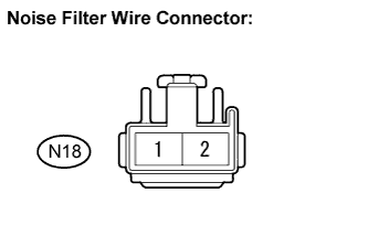
9. CHECK HARNESS AND CONNECTOR (NOISE FILTER POWER SOURCE)
Disconnect the noise filter connector. Measure the voltage according to the value(s) in the table below.
Standard voltage:
Tester Connection
Condition
Specified Condition
N18-1 - Body ground
Ignition switch on (IG) and rear window defogger switch on
10 to 14 V
Result:
Result
Proceed to
OK
A
NG
B
A
B
10. INSPECT RR DEF RELAY
Disconnect the RR DEF relay.
Measure the resistance according to the value(s) in the table below.
Standard resistance:
Tester Condition
Specified Condition
3 - 4
Below 1 Ω
3 - 5
10 kΩ or higher
3 - 5
Below 1 Ω
NG
OK
11. CHECK HARNESS AND CONNECTOR (RR DEF RELAY - BATTERY POSITIVE AND BODY GROUND)
Measure the voltage and resistance according to the value(s) in the table below.
Standard resistance:
Tester Connection
Condition
Specified Condition
4 - Body ground
Always
Below 1 Ω
Standard voltage:
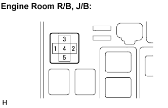
Engine room R/B, J/B:
Tester Connection
Condition
Specified Condition
5 - Body ground
Always
10 to 14 V
NG
REPAIR OR REPLACE RR DEF FUSE, HARNESS OR CONNECTOR
OK
REPAIR OR REPLACE HARNESS OR CONNECTOR (RR DEF RELAY - NOISE FILTER)
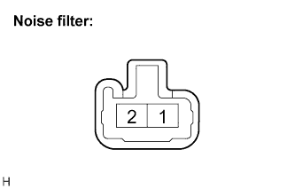
12. INSPECT NOISE FILTER
Disconnect the noise filter connector. Measure the resistance according to the value(s) in the table below.
Standard resistance:
Tester Connection
Condition
Specified Condition
1 - 2
Always
Below 1 Ω
1 - Body ground
Always
10 kΩ or higher
NG
OK
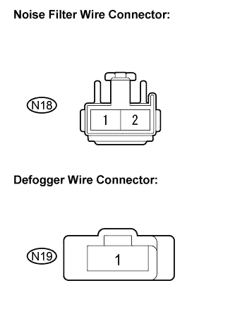
13. CHECK HARNESS AND CONNECTOR (NOISE FILTER - DEFOGGER WIRE CONNECTOR)
Measure the resistance according to the value(s) in the table below.
Standard resistance:
Tester Connection
Condition
Specified Condition
N18-2 - N19-1
Always
Below 1 Ω
N18-2 - Body ground
Always
10 kΩ or higher
NG
REPAIR OR REPLACE HARNESS OR CONNECTOR
OK
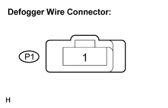
14. CHECK HARNESS AND CONNECTOR (DEFOGGER WIRE CONNECTOR - BODY GROUND)
Measure the resistance according to the value(s) in the table below.
Standard resistance:
Tester Connection
Condition
Specified Condition
P1-1 - Body ground
Always
Below 1 Ω
NG
REPAIR OR REPLACE HARNESS OR CONNECTOR
OK
REPAIR OR REPLACE REAR WINDOW DEFOGGER WIRE