TERMINALS OF ECU
System information · Vehicles built Oct 2006 – May 2009
Versions by build date: Oct 2006 – May 2009 from Jun 2009
| CHECK MAIN BODY ECU (INSTRUMENT PANEL J/B) |
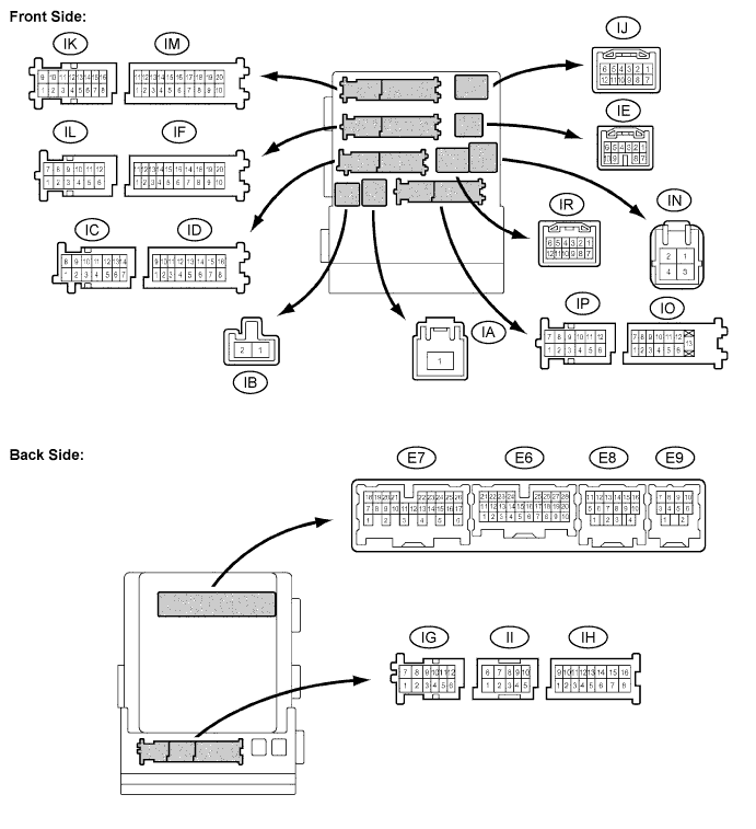

Disconnect the IA, IF and IM J/B connectors.
Measure the voltage and resistance between the specified terminals of the wire harness side connectors and body ground.
- Standard voltage:
Symbols
Wiring Color
Terminal Description
Condition
Specified Condition
IA-1 - Body ground
B - Body ground
Battery power supply
Always
10 to 14 V
- Standard resistance:
Symbols
Wiring Color
Terminal Description
Condition
Specified Condition
GND1 (IF-10) - Body ground
W-B - Body ground
Ground
Always
Below 1 Ω
GND2 (IM-9) - Body ground
W-B - Body ground
Ground
Always
Below 1 Ω
Reconnect the IA, IF, and IM J/B connectors.
Measure the resistance and voltage between the specified terminals of the J/B connectors and body ground.
- Standard resistance:
Symbols
Wiring Color
Terminal Description
Condition
Specified Condition
CLTE (E6-18)*5 - Body ground
BR - Body ground
Automatic light control sensor ground
Always
Below 1 Ω
- Standard voltage:
Symbols
Wiring Color
Terminal Description
Condition
Specified Condition
HRLY (ID-3) - Body ground
P - Body ground
Headlight relays drive output
Light control switch in HEAD
Below 1 V
Light control switch OFF
10 to 14 V
DIM (ID-9) - Body ground
V - Body ground
High beam headlight relay drive output
Low beam headlights are on and dimmer switch in HIGH, or dimmer switch in HIGH FLASH
Below 1 V
Dimmer switch in LOW
10 to 14 V
HU (IG-5) - Body ground
LG - Body ground
Dimmer switch HIGH signal input
Dimmer switch in HIGH
Below 1 V
Dimmer switch in LOW
10 to 14 V
ILE (II-10)*1 - Body ground
BR - Body ground
Interior light and ignition key cylinder light drive output
Interior light and ignition key cylinder light ON
Below 1 V
Interior light and ignition key cylinder light OFF
10 to 14 V
LCTY (IO-7) - Body ground
LG - Body ground
Rear left door courtesy switch input
Rear left door open
Below 1 V
Rear left door closed
10 to 14 V
LSWL (IP-5)*2, *5 - Body ground
GR - Body ground
Rear left door lock position switch input
Rear left door locked
10 to 14 V
Rear left door unlocked
Below 1 V
RCTY (E6-5)*1 - Body ground
GR - Body ground
Rear right door courtesy switch input
Rear right door open
Below 1 V
Rear right door closed
10 to 14 V
LSWR (E6-5)*2, *5 - Body ground
V - Body ground
Rear right door lock position switch input
Rear right door locked
10 to 14 V
Rear right door unlocked
Below 1 V
RCTY (E6-7)*2 - Body ground
GR - Body ground
Rear right door courtesy switch input
Rear right door open
Below 1 V
Rear right door closed
10 to 14 V
HEAD (E6-17) - Body ground
P- Body ground
Light control switch HEAD signal input
Light control switch in HEAD
Below 1 V
Light control switch not in HEAD
10 to 14 V
CLTS (E6-19)*5 - Body ground
G- Body ground
Automatic light control sensor signal input
Ignition switch off
Below 1 V
Automatic light control system operates
Pulse generation
(See waveform 1)
CLTB (E6-20)*5 - Body ground
B - Body ground
Automatic light control sensor power supply output
Ignition switch off
Below 1 V
Ignition switch on (IG) and light control switch in AUTO
10 to 14 V
PCTY (E6-21) - Body ground
Y*4 - Body ground
L*5 - Body ground
Passenger side door courtesy switch input
Passenger side door open
Below 1 V
Passenger side door closed
10 to 14 V
LGCY (E6-25) - Body ground
W - Body ground
Luggage compartment door courtesy switch input
Luggage compartment door open
Below 1 V
Luggage compartment door closed
10 to 14 V
LSWP (E6-27) - Body ground
LG*4 - Body ground
L*5 - Body ground
Passenger side and rear door lock position switches input*1
Passenger side and rear LH and rear RH doors locked
10 to 14 V
Passenger side or rear LH or rear RH door unlocked
Below 1 V
Passenger side door lock position switch input*2
Passenger side door locked
10 to 14 V
Passenger side door unlocked
Below 1 V
FFOG (E6-28)*3 - Body ground
V - Body ground
Front fog light switch input
Front fog light switch ON
Below 1 V
Front fog light switch OFF
10 to 14 V
FFGO (E7-4)*3 - Body ground
R - Body ground
Front fog light relay drive output
Taillights ON and front fog light switch ON
Below 1 V
Front fog light switch OFF or taillights OFF
10 to 14 V
LSWD (E7-9) - Body ground
L*4 - Body ground
Y*5 - Body ground
Driver side door lock position switch input
Driver side door locked
10 to 14 V
Driver side door unlocked
Below 1 V
HF (E7-13) - Body ground
R - Body ground
Dimmer switch HIGH FLASH signal input
Dimmer switch in HIGH FLASH position
Below 1 V
Dimmer switch not in HIGH FLASH position
10 to 14 V
A (E7-21)*5 - Body ground
G - Body ground
Light control switch AUTO signal input
Light control switch in AUTO
Below 1 V
Light control switch not in AUTO
10 to 14 V
TAIL (E7-23) - Body ground
B - Body ground
Light control switch TAIL signal input
Light control switch in TAIL or HEAD
Below 1 V
Light control switch in neither TAIL nor HEAD
10 to 14 V
DCTY (E7-24) - Body ground
L*4 - Body ground
Y*5 - Body ground
Driver side door courtesy switch input
Driver side door open
Below 1 V
Driver side door closed
10 to 14 V
CANH (E8-5) - Body ground
B - Body ground
CAN communication line H
Ignition switch on (IG)
Pulse generation
Ignition switch off
Below 1 V
CANL (E8-6) - Body ground
W - Body ground
CAN communication line L
Ignition switch on (IG)
Pulse generation
Ignition switch off
Below 1 V
- HINT:
- *1: without Smart Entry and Start System
- *2: with Smart Entry and Start System
- *3 with Front Fog Light
- *4: for LHD
- *5: for RHD
- *1: without Smart Entry and Start System
Waveform 1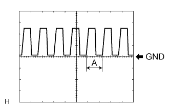
Item
Contents
Tool setting
5 V/DIV., 5 ms./DIV.
- HINT:
- If the ambient light becomes brighter, width A becomes narrower.
| CHECK HEADLIGHT LEVELING ECU |
Disconnect the A20 ECU connector.
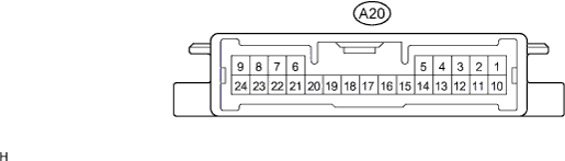
Measure the voltage and resistance between the specified terminals of the wire harness side connectors and body ground.
- Standard voltage:
Symbols (Terminal No.)
Wiring Color
Terminal Description
Condition
Specified Condition
IG (A20-1) - Body ground
GR - Body ground
IG power supply
Ignition switch off
Below 1 V
Ignition switch on (IG)
10 to 14 V
- Standard resistance:
Symbols (Terminal No.)
Wiring Color
Terminal Description
Condition
Specified Condition
E1 (A20-9) - Body ground
W - Body ground
Ground
Always
Below 1 Ω
Reconnect the A20 ECU connector.
Measure the resistance and voltage according to the value(s) in the table below.
- Standard resistance:
Symbols (Terminal No.)
Wiring Color
Terminal Description
Condition
Specified Condition
SGR (A20-21) - E1 (A20-9)
G - W
Rear height control sensor ground
Always
Below 1 Ω
RH- (A20-23) - E1 (A20-9)
V - W
Leveling motor RH ground
Always
Below 1 Ω
LH- (A20-24) - E1 (A20-9)
GR - W
Leveling motor LH ground
Always
Below 1 Ω
- Standard voltage:
Symbols (Terminal No.)
Wiring Color
Terminal Description
Condition
Specified Condition
B2 (A20-3) - E1 (A20-9)
P - W
Low beam headlight signal input
Low beam headlights ON
Below 1.5 V
Low beam headlights OFF
Above 5 V
SPDL (A20-5) - E1 (A20-9)
W - W
Initialization signal input
Terminal LVL and terminal GND of DLC3 connected
Below 1 V
Terminal LVL and terminal GND of DLC3 not connected
Approx. 5 V
WNG (A20-6) - E1 (A20-9)
P - W
Warning indicator drive output
Warning indicator ON
10 to 14 V
Warning indicator OFF
Below 1 V
RH+ (A20-10) - E1 (A20-9)
R - W
Leveling motor RH power supply
Ignition switch off
Below 1 V
Ignition switch on (IG)
10 to 16 V
LH+ (A20-11) - E1 (A20-9)
Y - W
Leveling motor LH power supply
Ignition switch off
Below 1 V
Ignition switch on (IG)
10 to 16 V
SBR (A20-12) - SGR (A20-21)
B - G
Rear height control sensor power supply
Ignition switch off
Below 1 V
Ignition switch on (IG)
4.75 to 5.25 V
SPDR (A20-16) - E1 (A20-9)
Y - W
Vehicle speed signal input
Vehicle is driven at approx. 20 km/h
Pulse generation
(See waveform 1)
RHE (A20-17) - E1 (A20-9)
LG - W
Leveling motor RH operation signal input
With low beam headlights ON, vehicle height not changed
Below 1 V
With low beam headlights ON, change vehicle height and keep for more than 3 seconds.
1.0 to 14.4 V
LHE (A20-18) - E1 (A20-9)
W - W
Leveling motor LH operation signal input
With low beam headlights ON, vehicle height not changed
Below 1 V
With low beam headlights ON, change vehicle height and keep for more than 3 seconds.
1.0 to 14.4 V
SHRL (A20-19) - SGR (A20-21)
L - G
Rear height control sensor signal input
Ignition switch off
Below 1 V
Ignition switch on (IG)
0.5 to 4.5 V
Waveform 1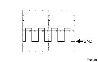
Item
Contents
Tool setting
2 V/DIV., 2 ms./DIV.
| CHECK AFS ECU |
Disconnect the A61 ECU connector.

Measure the voltage and resistance between the specified terminals of the wire harness side connectors and body ground.
- Standard voltage:
Symbols (Terminal No.)
Wiring Color
Terminal Description
Condition
Specified Condition
IGS (A61-14) - Body ground
Y - Body ground
Swivel motor power supply
Ignition switch off
Below 1 V
Ignition switch on (IG)
10 to 14 V
IGSR (A61-15) - Body ground
GR - Body ground
AFS ECU power supply
Ignition switch off
Below 1 V
Ignition switch on (IG)
10 to 14 V
- Standard resistance:
Symbols (Terminal No.)
Wiring Color
Terminal Description
Condition
Specified Condition
EIS (A61-22) - Body ground
W - Body ground
AFS ECU ground
Always
Below 1 Ω
Reconnect the A61 ECU connector.
Measure the resistance and voltage according to the value(s) in the table below.
- Standard resistance:
Symbols (Terminal No.)
Wiring Color
Terminal Description
Condition
Specified Condition
A6N (A61-21) - EIS (A61-22)
G - W
Rear height control sensor ground
Always
Below 1 Ω
SMGL (A61-23) - EIS (A61-22)
GR - W
Swivel motor LH ground
Always
Below 1 Ω
SMGR (A61-24) - EIS (A61-22)
P - W
Swivel motor RH ground
Always
Below 1 Ω
LH- (A61-27) - EIS (A61-22)
GR - W
Leveling motor LH ground
Always
Below 1 Ω
RH- (A61-28) - EIS (A61-22)
V - W
Leveling motor RH ground
Always
Below 1 Ω
- Standard voltage:
Symbols (Terminal No.)
Wiring Color
Terminal Description
Condition
Specified Condition
SMBL (A61-1) - EIS (A61-22)
Y - W
Swivel motor LH power supply
Ignition switch off
Below 1 V
Ignition switch on (IG)
10 to 14 V
SMBR (A61-2) - EIS (A61-22)
G - W
Swivel motor LH power supply
Ignition switch off
Below 1 V
Ignition switch on (IG)
10 to 14 V
LH+ (A61-3) - EIS (A61-22)
Y - W
Leveling motor RH power supply
Ignition switch off
Below 1 V
Ignition switch on (IG)
10 to 16 V
RH+ (A61-4) - EIS (A61-22)
R - W
Leveling motor LH power supply
Ignition switch off
Below 1 V
Ignition switch on (IG)
10 to 14 V
AFWG (A61-7) - EIS (A61-22)
W - W
Initialization signal
Terminal LVL and terminal GND of DLC3 connected
Below 1 V
Terminal LVL and terminal GND of DLC3 not connected
10 to 14 V
SMR (A61-10) - EIS (A61-22)
L - W
Swivel motor RH LIN communication
Ignition switch off
Below 1 V
Ignition switch on (IG)
Pulse generation
RHE (A61-11) - EIS (A61-22)
LG - W
Leveling motor RH LIN communication
Ignition switch off
Below 1 V
Ignition switch on (IG)
Pulse generation
MPX1 (A61-12) - EIS (A61-22)
R - W
CAN communication
Ignition switch off
Below 1 V
Ignition switch on (IG)
Pulse generation
MPX2 (A61-13) - EIS (A61-22)
W - W
CAN communication
Ignition switch off
Below 1 V
Ignition switch on (IG)
Pulse generation
A6M (A61-18) - A6N (A61-21)
B - G
Rear height control sensor power supply
Ignition switch off
Below 1 V
Ignition switch on (IG)
4.5 to 5.5 V
A6E (A61-19) - A6N (A61-21)
L - G
Rear height control sensor signal
Ignition switch off
Below 1 V
Ignition switch on (IG)
0 to 4.5 V
SML (A61-29) - EIS (A61-22)
W - W
Swivel motor LH LIN communication
Ignition switch off
Below 1 V
Ignition switch on (IG)
Pulse generation
LHE (A61-30) - EIS (A61-22)
W - W
Leveling motor LH LIN communication
Ignition switch off
Below 1 V
Ignition switch on (IG)
Pulse generation
MSW (A61-32) - EIS (A61-22)
BR - W
AFS OFF switch signal
Ignition switch on (IG), AFS OFF switch OFF (not pushed)
10 to 14 V
Ignition switch on (IG), AFS OFF switch ON (pushed)
Below 1 V