B1272 Power Seat ECU Communication Stop
Diagnostic trouble codes · Vehicles built from Jun 2009
Versions by build date: Oct 2006 – May 2009 from Jun 2009
DESCRIPTION
The main body ECU will store this DTC when no signals can be received from the seat position control ECU while the CAN MS main bus is normal.| DTC No. |
DTC Detection Condition |
Trouble Area |
| B1272 |
No communication from seat position control ECU (Front LH side) continues |
|
WIRING DIAGRAM
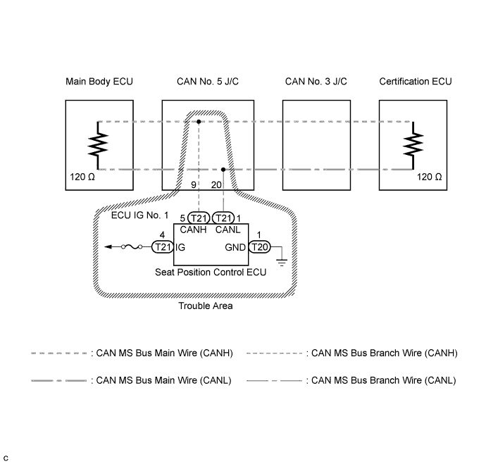

INSPECTION PROCEDURE
- NOTICE:
- Turn the engine switch off before measuring the resistances of CAN bus main wires and CAN bus branch wires.
- After the engine switch is turned off, check that the key reminder warning system and lighting system are not operating.
- Before measuring the resistance, leave the vehicle as is for at least 1 minute and do not operate the engine switch, any other switches, or the doors. If any doors need to be opened in order to check connectors, open the doors and leave them open.
- Turn the engine switch off before measuring the resistances of CAN bus main wires and CAN bus branch wires.
- HINT:
- Operating the engine switch, any other switches, or a door triggers related ECU and sensor communication on the CAN. This communication will cause the resistance value to change.
| 1. CHECK DTC |

Check for DTCs.
- HINT:
- If CAN MS bus communication error DTC B2326 is output, troubleshoot for B2326 and check for malfunctions in the CAN MS main bus circuit (Click here).
- Result:
Result
Proceed to
B2326 is not output
A
B2326 is output
B
|
|
||||

| A | |
 |
| 2. CHECK CAN MS BUS WIRE (SEAT POSITION CONTROL ECU) |
Turn the engine switch off.
Disconnect connector T21 from the seat position control ECU for the front RH side.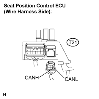
Measure the resistance according to the value(s) in the table below.
- Standard resistance:
Tester Connection
Condition
Specified Value
T21-5 (CANH) - T21-1 (CANL)
Engine switch off
54 to 69 Ω
|
|
||||
| OK | |
|
| 3. CHECK HARNESS AND CONNECTOR (POWER SOURCE CIRCUIT) |
Disconnect t connector T20 from the seat position control ECU for the front LH side.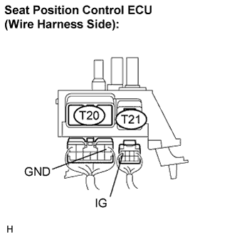
Measure the resistance according to the value(s) in the table below.
- Standard resistance:
Tester Connection
Condition
Specified Value
T20-1 (GND) - Body ground
Always
Below 1 Ω
Measure the voltage according to the value(s) in the table below.
- Standard voltage:
Tester Connection
Condition
Specified Value
T21-4 (IG) - Body ground
Engine switch on (IG)
10 to 14 V
|
|
||||
| OK | ||
 |
||
| ||