2006-2011 Camry Aurion · Service Manual BODY ELECTRICAL

REMOVAL

Removal / installation · Vehicles built Oct 2006 – May 2009

Versions by build date: Oct 2006 – May 2009 from Jun 2009


1. PRECAUTION

CAUTION:
Be sure to read "PRECAUTION" thoroughly before servicing (Click here).


2. ALIGN FRONT WHEELS FACING STRAIGHT AHEAD

3. DISCONNECT CABLE FROM NEGATIVE BATTERY TERMINAL

NOTICE:
Wait for 90 seconds after disconnecting the cable to prevent airbag deployment.


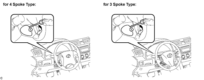
4. REMOVE LOWER NO. 3 STEERING WHEEL COVER

  1. Using a screwdriver, disengage the claw and remove the No. 3 lower steering wheel cover.

    C146012E01

    HINT:
    Tape up the screwdriver tip before use.


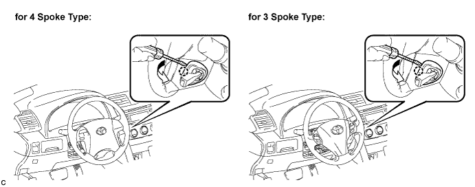
5. REMOVE LOWER NO. 2 STEERING WHEEL COVER

  1. Using a screwdriver, disengage the claw and remove the No. 2 lower steering wheel cover.

    C146013E01

    HINT:
    Tape up the screwdriver tip before use.


6. REMOVE STEERING PAD

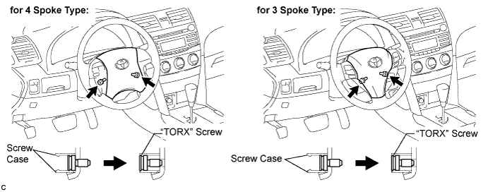
  1. Using a "TORX" socket (T30), loosen the 2 "TORX" screws until the groove along the screw circumference catches on the screw case.

    C146014E01

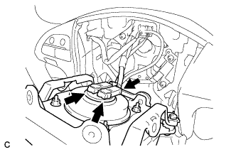
  1. C133859E01
    Pull out the steering pad from the steering wheel assembly and support the steering pad with one hand.

    NOTICE:
    When removing the steering pad, do not pull the airbag wire harness.

  1. Disconnect the horn connector from the steering pad.

  1. Disconnect the 2 airbag connectors and remove the steering pad.

    NOTICE:
    When handling the airbag connector, take care not to damage the airbag wire harness.


7. REMOVE STEERING WHEEL ASSEMBLY
  1. Remove the steering wheel assembly set nut.

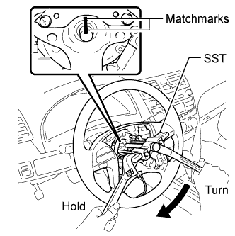
  1. Put matchmarks on the steering wheel assembly and the steering main shaft.

  1. Disconnect the connectors from the spiral cable.

  1. C145839E01
    Using SST, remove the steering wheel assembly.
    SST
    09950-50013   (09951-05010, 09952-05010, 09953-05020, 09954-05031)


8. REMOVE FRONT DOOR SCUFF PLATE RH

HINT:
Use the same procedure for the RH side and the LH side (Click here).


9. REMOVE COWL SIDE TRIM SUB-ASSEMBLY RH

HINT:
Use the same procedure for the RH side and the LH side (Click here).


10. REMOVE LOWER NO. 1 INSTRUMENT PANEL FINISH PANEL

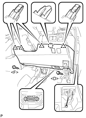
  1. B158913E01
    Remove the bolt <D> and the screw <F>.

  1. Disengage the 2 claws and the DLC3.

  1. Disconnect the hood lock control cable assembly.

  1. Disengage the claw and the 4 clips.

  1. Remove the air hose, disconnect each connector, and then remove the lower No. 1 instrument panel finish panel.


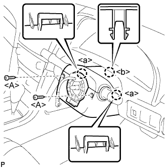
11. REMOVE STEERING COLUMN COVER

  1. B158914E01
    Remove the 2 screws <A>.

  1. Disengage the 2 claws <a> and remove the lower steering column cover.

  1. Disengage the claw <b> and remove the upper steering column cover.


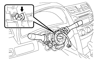
12. REMOVE TURN SIGNAL SWITCH ASSEMBLY WITH SPIRAL CABLE SUB-ASSEMBLY
  1. Disconnect the connectors from the turn signal switch assembly with spiral cable sub-assembly.

  1. C145843
    Using pliers, grip the claws of the clip and remove the turn signal switch assembly with spiral cable sub-assembly.


13. REMOVE NO. 1 INSTRUMENT PANEL SUB-ASSEMBLY

  1. B158916
    Disengage the 3 claws and the 2 clips.

  1. Disconnect each connector and remove the No. 1 instrument panel sub-assembly.


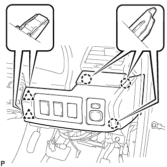
14. REMOVE LOWER INSTRUMENT PANEL FINISH PANEL (w/o Smart Entry and Start System)

  1. B158917
    Disengage the 2 claws and 2 clips, and then remove the lower instrument panel finish panel.


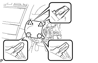
15. REMOVE LOWER INSTRUMENT PANEL FINISH PANEL (w/ Smart Entry and Start System)

  1. B158918
    Disengage the 2 claws and 2 clips, and then remove the lower instrument panel finish panel.

  1. Disconnect the connector.


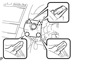
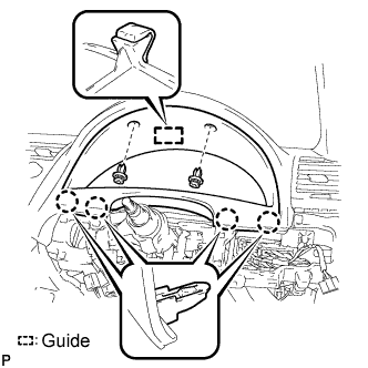
16. REMOVE INSTRUMENT CLUSTER FINISH PANEL SUB-ASSEMBLY

  1. B158919E01
    Remove the 2 clips.

  1. Disengage the guide and 4 claws, and then remove the instrument cluster finish panel sub-assembly.


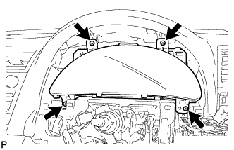
17. REMOVE COMBINATION METER ASSEMBLY

  1. B158920
    Remove the 4 screws <B>, <C> or <H>.

  1. Disconnect each connector and remove the combination meter assembly.


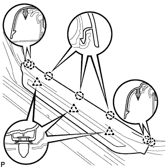
18. REMOVE FRONT DOOR SCUFF PLATE LH

  1. B132067
    Disengage the 7 claws and 3 clips, and remove the front door scuff plate LH.


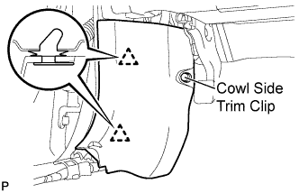
19. REMOVE COWL SIDE TRIM SUB-ASSEMBLY LH

  1. B132116E01
    Remove the cowl side trim clip.

  1. Disengage the 2 clips and remove the cowl side trim sub-assembly LH.


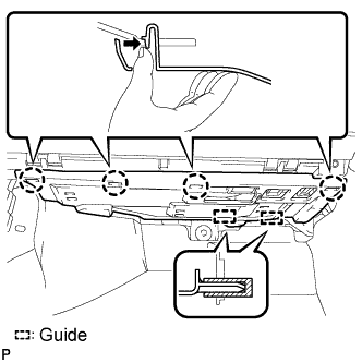
20. REMOVE INSTRUMENT PANEL NO. 2 UNDER COVER SUB-ASSEMBLY

  1. B158921E01
    Disengage the 4 claws.

  1. Disengage the 2 guides and remove the No. 2 under cover sub-assembly.


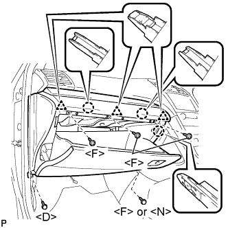
21. REMOVE LOWER INSTRUMENT PANEL SUB-ASSEMBLY

  1. B158922E01
    Remove the bolt <D>.

  1. Remove the screw <F> or <N>.

  1. Remove the 3 screws <F>.

  1. Disengage the 3 claws and the 3 clips, and then remove the lower instrument panel sub-assembly.


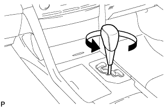
22. REMOVE SHIFT LEVER KNOB SUB-ASSEMBLY

  1. B159322
    Turn the shift lever knob counterclockwise and remove the shift lever knob sub-assembly.


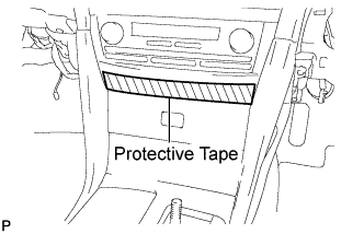
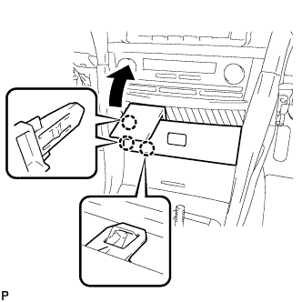
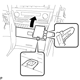
23. REMOVE UPPER CONSOLE PANEL FRONT GARNISH

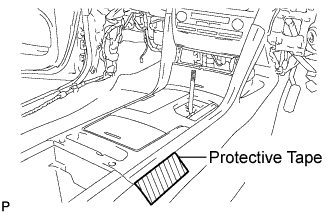
  1. B158924E01
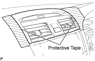
    Apply protective tape to the area shown in the illustration.

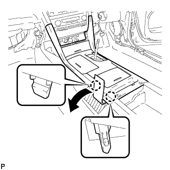
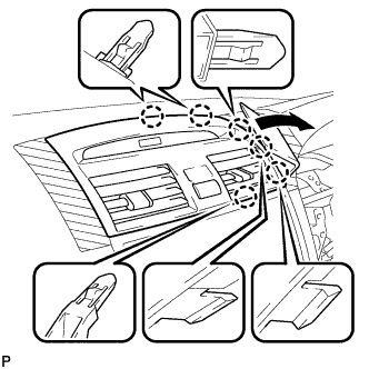
  1. B158926
    Using a moulding remover, disengage the 3 claws as shown in the illustration.

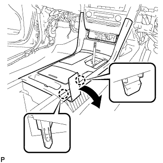
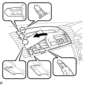
  1. B158925
    Using a moulding remover, disengage the 3 claws and remove the upper console panel front garnish as shown in the illustration.

  1. Disconnect each connector.


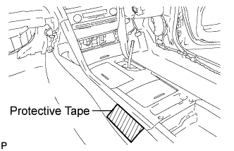
24. REMOVE UPPER CONSOLE PANEL SUB-ASSEMBLY

  1. B158929E01
    Apply protective tape to the area shown in the illustration.

  1. B158930
    Using a moulding remover, disengage the 2 claws as shown in the illustration.

  1. B158927E01
    Apply protective tape to the area shown in the illustration.

  1. B158928
    Using a moulding remover, disengage the 2 claws as shown in the illustration.

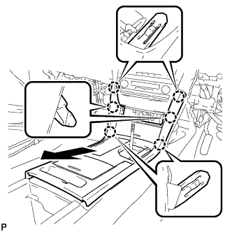
  1. B158931
    Disengage the 6 claws and remove the upper console panel sub-assembly as shown in the illustration.

  1. Disconnect the connector.


25. REMOVE INSTRUMENT PANEL NO. 2 REGISTER ASSEMBLY

  1. B158932E01
    Apply protective tape to the areas shown in the illustration.

  1. B158934
    Using a moulding remover, disengage the 6 claws as shown in the illustration.

  1. B158933
    Using a moulding remover, disengage the 5 claws as shown in the illustration.

  1. Disconnect each connector and remove the instrument panel No. 2 register assembly.


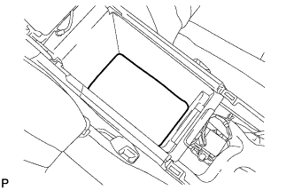
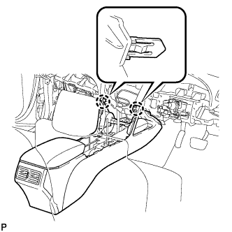
26. REMOVE CONSOLE BOX CARPET

  1. B158935
    Remove the console box carpet.


27. REMOVE CONSOLE BOX ASSEMBLY

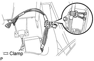
  1. B158936E01
    Disengage the clamp.

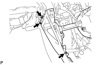
  1. B158938
    Remove the 3 screws <H>.

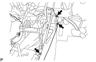
  1. B158937
    Remove the 3 screws <H>.

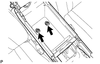
  1. B158939
    Remove the 2 bolts <I>.

  1. B158940
    Disengage the 2 claws and remove the console box assembly.


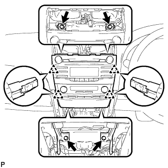
28. REMOVE RADIO RECEIVER WITH HEATER CONTROL PANEL ASSEMBLY (for Radio Receiver Type)

  1. E141626
    Remove the 4 bolts.

  1. Pull the radio receiver with heater control panel assembly toward the rear of the vehicle and disengage the 4 clips.

  1. Disconnect each connector and remove the radio receiver with heater control panel assembly.


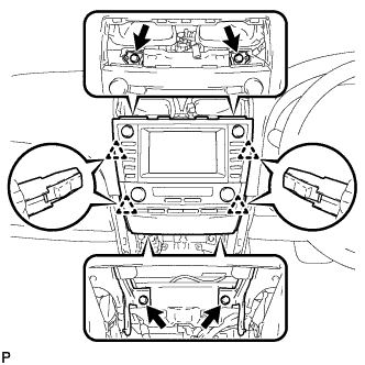
29. REMOVE NAVIGATION RECEIVER WITH HEATER CONTROL PANEL ASSEMBLY (w/ Navigation System)

  1. E137564
    Remove the 4 bolts.

  1. Pull the navigation receiver with heater control panel assembly toward the rear of the vehicle and disengage the 4 clips.

  1. Disconnect each connector and remove the navigation receiver with heater control panel assembly.


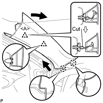
30. REMOVE FRONT PILLAR GARNISH LH

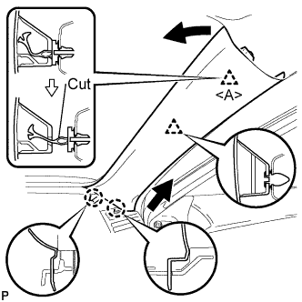
  1. B132056E01
    Pull the upper part of the garnish toward the inside of the cabin and disengage the 2 clips.

  1. Cut off the clip <A>.

  1. Disengage the 2 claws and remove the front pillar garnish LH.

  1. Remove the clip <A> from the vehicle body.

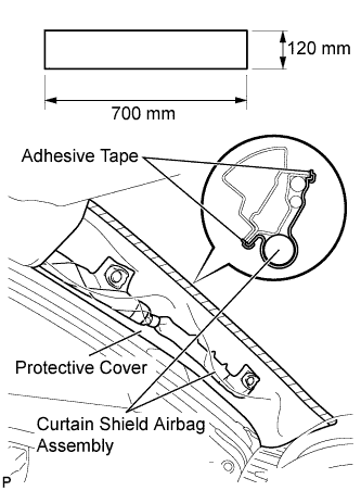
  1. B132100E02
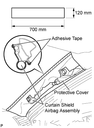
    Protect the curtain shield airbag assembly.

    1. Cover the airbag with a 700 mm (27.56 in.) x 120 mm (4.72 in.) cloth or piece of nylon and fix the ends of the cover with tape, as shown in the illustration.

      NOTICE:
      Cover the curtain shield airbag with a protective cover as soon as the front pillar garnish is removed.

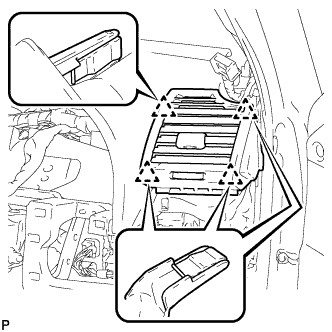
31. REMOVE INSTRUMENT PANEL NO. 1 REGISTER ASSEMBLY

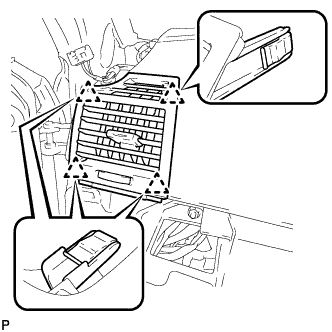
  1. B158943
    Disengage the 4 clips and remove the instrument panel No. 1 register assembly.


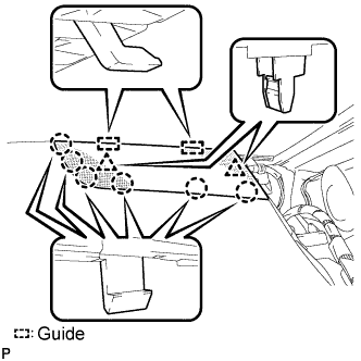
32. REMOVE INSTRUMENT PANEL NO. 1 SPEAKER PANEL SUB-ASSEMBLY

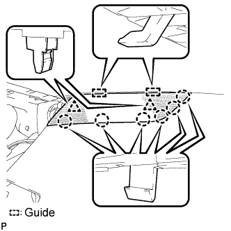
  1. B158945E01
    Disengage the 6 claws and the 2 clips.

  1. Disengage the 2 guides and remove the instrument panel No. 1 speaker panel sub-assembly.


33. REMOVE FRONT NO. 2 SPEAKER ASSEMBLY (for LH Side)

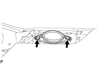
  1. E129167
    Remove the 2 bolts and front No. 2 speaker assembly.

  1. Disconnect the connector.


34. REMOVE FRONT PILLAR GARNISH RH

  1. B132055E01
    Pull the upper part of the garnish toward the inside of the cabin and disengage the 2 clips.

  1. Cut off the clip <A>.

  1. Disengage the 2 claws and remove the front pillar garnish RH.

  1. Remove the clip <A> from the vehicle body.

  1. B132099E02
    Protect the curtain shield airbag assembly.

    1. Cover the airbag with a 700 mm (27.56 in.) x 120 mm (4.72 in.) cloth or piece of nylon and fix the ends of the cover with tape, as shown in the illustration.

      NOTICE:
      Cover the curtain shield airbag with a protective cover as soon as the front pillar garnish is removed.

35. REMOVE INSTRUMENT PANEL NO. 3 REGISTER ASSEMBLY
  1. B158942
    Disengage the 4 clips and remove the instrument panel No. 3 register assembly.


36. REMOVE INSTRUMENT PANEL NO. 2 SPEAKER PANEL SUB-ASSEMBLY

  1. B158944E01
    Disengage the 6 claws and the 2 clips.

  1. Disengage the 2 guides and remove the instrument panel No. 2 speaker panel sub-assembly.


37. REMOVE FRONT NO. 2 SPEAKER ASSEMBLY (for RH Side)

HINT:
Use the same procedure for the RH side and the LH side (Click here).


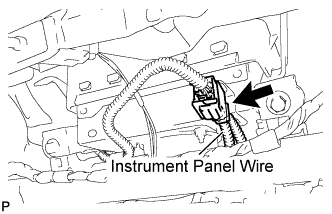
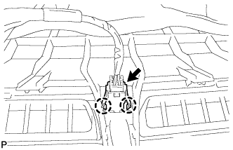
38. DISCONNECT INSTRUMENT PANEL WIRE ASSEMBLY

  1. C132564E01
    Disconnect the connector (yellow colored one).


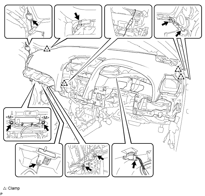
39. REMOVE INSTRUMENT PANEL SAFETY PAD ASSEMBLY
  1. Disengage each clamp.

  1. Disconnect each connector.

  1. Remove the bolt <E>.

  1. Remove the 2 passenger airbag bolts <M>.

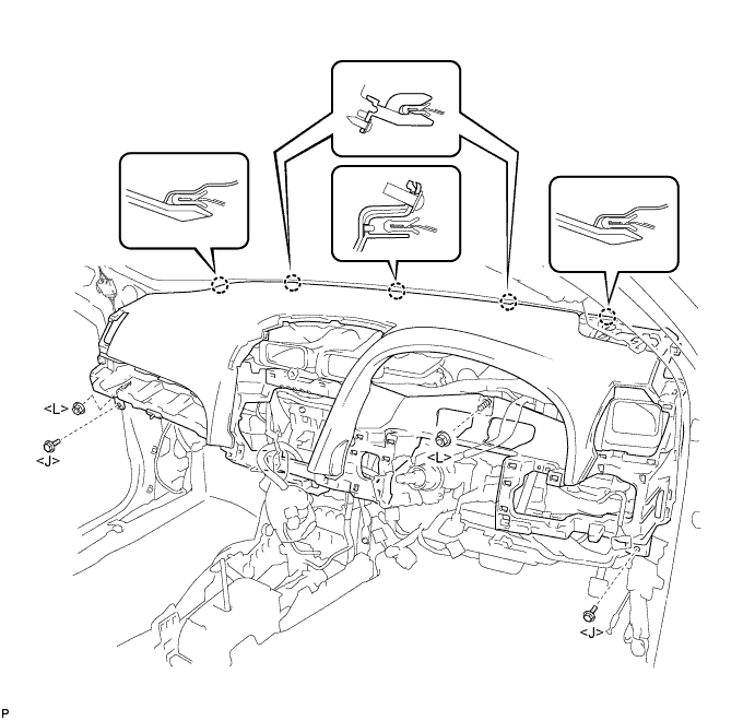
    B158948E01

  1. Remove the 2 bolts <J>.

  1. Remove the 2 nuts <L>.

  1. Disengage the 5 claws and remove the instrument panel safety pad assembly.

    B158947E01


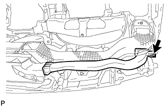
40. REMOVE SIDE NO. 1 DEFROSTER NOZZLE DUCT

  1. B158950
    Remove the screw <H> and the side No. 1 defroster nozzle duct.


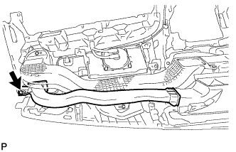
41. REMOVE SIDE NO. 2 DEFROSTER NOZZLE DUCT

  1. B158951
    Remove the screw <H> and the side No. 2 defroster nozzle duct.


42. REMOVE DEFROSTER NOZZLE ASSEMBLY

  1. B158952
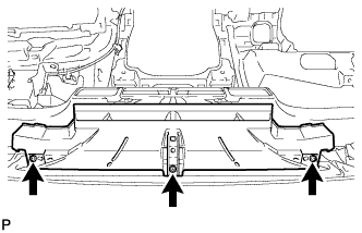
    Remove the 3 screws <H> and the defroster nozzle assembly.


43. REMOVE NO. 1 HEATER TO REGISTER DUCT

  1. B158953
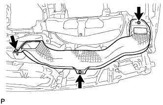
    Remove the 3 screws <H> and the No. 1 heater to register duct.


44. REMOVE NO. 3 HEATER TO REGISTER DUCT

  1. B158954
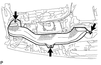
    Remove the 3 screws <H> and the No. 3 heater to register duct.


45. REMOVE NO. 2 HEATER TO REGISTER DUCT

  1. B158955
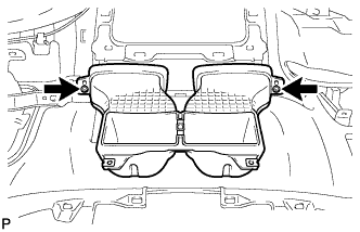
    Remove the 2 screws <H> and the No. 2 heater to register duct.


46. REMOVE AUTOMATIC LIGHT CONTROL SENSOR

  1. E135407
    Disconnect the connector.

  1. Disengage the 2 claws and remove the automatic light control sensor.

← ON-VEHICLE INSPECTION (from Jun 2009)REMOVAL (from Jun 2009) →