Indicator Circuit
Circuit diagnosis · Vehicles built from Jun 2009
DESCRIPTION
When the clearance sonar main switch is turned on, an ON signal is sent to the clearance warning ECU assembly and the indicator on the clearance sonar main switch comes on.WIRING DIAGRAM
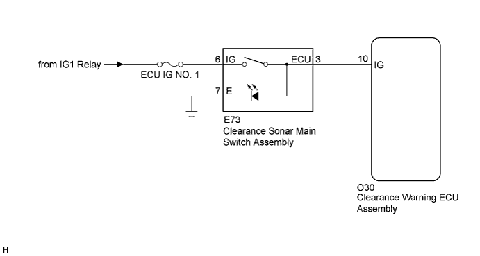

INSPECTION PROCEDURE
| 1. CHECK HARNESS AND CONNECTOR (CLEARANCE SONAR MAIN SWITCH - BODY GROUND) |

Disconnect the E73 connector from the clearance sonar main switch assembly.
Measure the resistance according to the value(s) in the table below.
- Standard Resistance:
Tester Connection
Condition
Specified Condition
E73-7 (E) - Body ground
Always
Below 1 Ω
|
|
||||

| OK | ||
 |
||
| ||