Door Control Receiver Circuit
Circuit diagnosis · Vehicles built Oct 2006 – May 2009
Versions by build date: Oct 2006 – May 2009 from Jun 2009
DESCRIPTION
- The electrical key antenna and the door control receiver are used as antennas for the entry and wireless door lock functions of the smart entry and start system.
- The certification ECU decodes the requested smart entry and start system operation by identifying a key code based on electric waves received via the electrical key antenna and the door control receiver. The ECU then sends a command, according to the requested operation, to each ECU. (e.g. If door lock operation is requested, the ECU sends a door lock command to the main body ECU.)
WIRING DIAGRAM
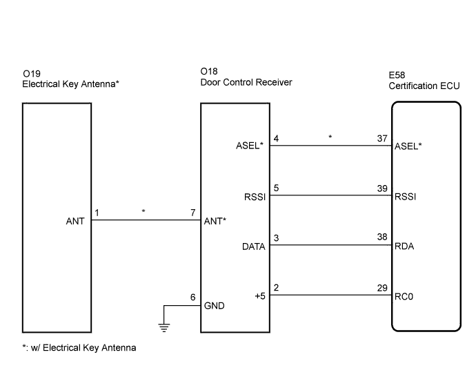

INSPECTION PROCEDURE
| 1. INSPECT CERTIFICATION ECU (DOOR CONTROL RECEIVER POWER SOURCE) |

Measure the voltage according to value(s) in the table below.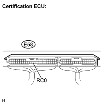
- Standard voltage:
Tester Connection
Condition
Specified Condition
E58-29 (RC0) - Body ground
Engine switch off, all doors closed and transmitter switch not pressed
Below 1 V
Engine switch off, all doors closed and transmitter switch pressed
4.6 to 5.4 V
|
|
||||

| OK | |
 |
| 2. INSPECT DOOR CONTROL RECEIVER (DOOR CONTROL RECEIVER BODY GROUND) |
Disconnect the O18 receiver connector.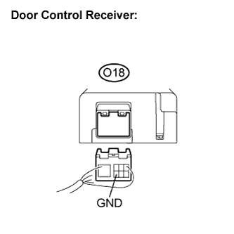
Measure the resistance according to the value(s) in the table below.
- Standard resistance:
Tester Connection
Condition
Specified Condition
O18-6 (GND) - Body ground
Always
Below 1 Ω
|
|
||||
| OK | |
|
| 3. CHECK HARNESS AND CONNECTOR (CERTIFICATION ECU - DOOR CONTROL RECEIVER) |
Disconnect the E58 ECU connector.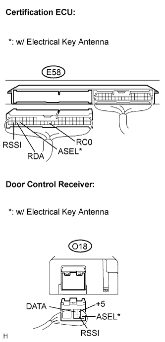
Measure the resistance according to the value(s) in the table below.
- Standard resistance:
Tester Connection (Symbols)
Condition
Specified Condition
E58-37 (ASEL) - O18-4 (ASEL)*
Always
Below 1 Ω
E58-39 (RSSI) - O18-5 (RSSI)
Always
Below 1 Ω
E58-38 (RDA) - O18-3 (DATA)
Always
Below 1 Ω
E58-29 (RC0) - O18-2 (+5)
Always
Below 1 Ω
E58-37 (ASEL) - Body ground*
Always
10 kΩ or higher
E58-39 (RSSI) - Body ground
Always
10 kΩ or higher
E58-38 (RDA) - Body ground
Always
10 kΩ or higher
E58-29 (RC0) - Body ground
Always
10 kΩ or higher
- Result:
Result
Proceed to
OK (w/ Electrical Key Antenna)
A
OK (w/o Electrical Key Antenna)
B
NG
C
|
|
||||
|
|
||||

| A | |
|
| 4. CHECK HARNESS AND CONNECTOR (DOOR CONTROL RECEIVER - ELECTRICAL KEY ANTENNA) |
Disconnect the O19 antenna connector.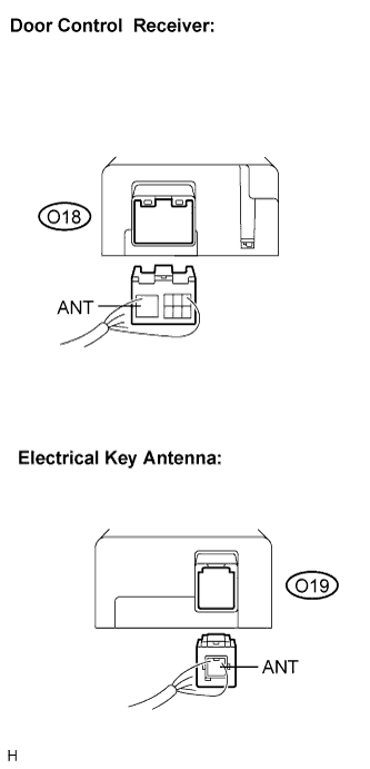
Measure the resistance according to the value(s) in the table below.
- Standard resistance:
Tester Connection (Symbols)
Condition
Specified Condition
O18-7 (ANT) - O19-1 (ANT)
Always
Below 1 Ω
O18-7 (ANT) - Body ground
Always
10 kΩ or higher
|
|
||||
| OK | |
|
| 5. CHECK AND REPLACE DOOR CONTROL RECEIVER |
Replace the receiver.
Check that the entry LOCK/UNLOCK function operates normally.
- OK:
- Entry LOCK/UNLOCK function operates normally.
- Result:
Result
Proceed to
NG (w/ Electrical Key Antenna)
A
NG (w/o Electrical Key Antenna)
B
OK
C
|
|
||||
|
|
||||
| A | |
|
| 6. CHECK AND REPLACE ELECTRICAL KEY ANTENNA |
Replace the antenna.
Check that the entry LOCK/UNLOCK function operates normally.
- OK:
- Entry LOCK/UNLOCK function operates normally.
|
|
||||
| NG | ||
 |
||
| ||