P0500 Vehicle Speed Sensor "A"
Diagnostic trouble codes · Vehicles built from Oct 2006
DESCRIPTION
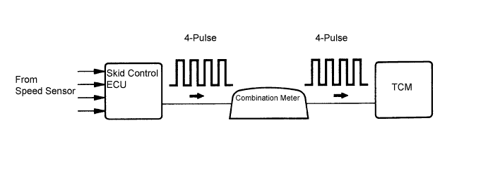
The speed sensors detect the wheel speed and send the appropriate signals to the skid control ECU. The skid control ECU converts these wheel speed signals into a 4-pulse signal and outputs it to the TCM via the combination meter. The TCM determines the vehicle speed based on the frequency of these pulse signals.- HINT:
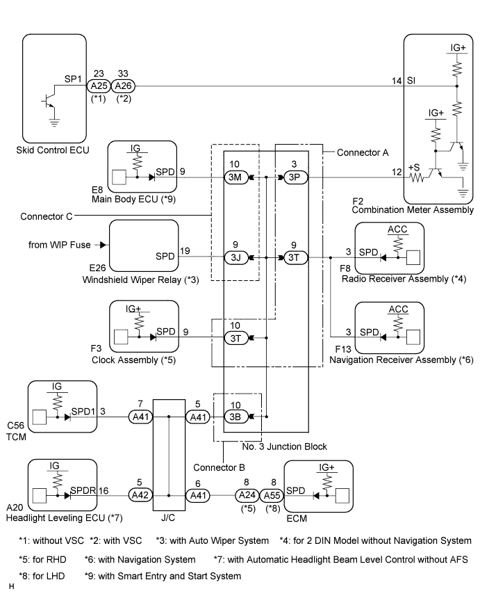
- A voltage of 12 V or 5 V is output from the combination meter assembly and then input to the skid control ECU. A voltage of 12 V or 5 V is output from each ECU or relay and then input to the combination meter assembly. The signal is changed to a pulse signal at the transistor in the combination meter assembly.
- Each ECU controls the respective system based on the pulse signal. If a short occurs in any of the ECUs or in the wire harness connected to an ECU, all systems in the diagram below will not operate normally.

| DTC No. |
DTC Detection Condition |
Trouble Area |
| P0500 |
When the ECT sensor is normal and the counter gear speed is 300 rpm or more, the vehicle speed signal is not input for 2 seconds or more. |
|
MONITOR DESCRIPTION
The TCM assumes that the vehicle is being driven when the transmission counter gear indicates more than 300 rpm and over 30 seconds have passed since the park/neutral position switch was turned off. If there is no signal from the vehicle speed sensor with these conditions satisfied, the TCM concludes that the vehicle speed sensor is malfunctioning. The TCM will turn on the MIL and a DTC will be set.WIRING DIAGRAM
INSPECTION PROCEDURE
| 1. INSPECT COMBINATION METER ASSEMBLY |

The circuits that send vehicle speed signals to this system are inspected in the meter system.
During inspection for the meter section, if there is an instruction that indicates to go back to inspections for each system, proceed to the next step.
| NEXT | |
 |
| 2. CHECK HARNESS AND CONNECTOR (COMBINATION METER - TCM) |
Remove the F2 and TCM connectors.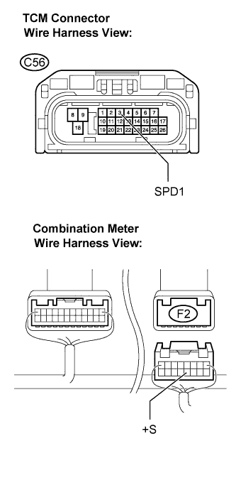
Measure the resistance according to the value(s) in the table below.
- Standard resistance:
Tester Connection
Condition
Specified Condition
+S (F2-12) - SPD1 (C56-3)
Always
Below 1 Ω
|
|
||||

| OK | ||
 |
||
| ||
| 3. CHECK HARNESS AND CONNECTOR (TCM - NO. 3 J/B) |
Remove the 3B No. 3 J/B connector.
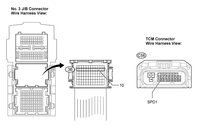
Measure the resistance according to the value(s) in the table below.
- Standard resistance:
Tester Connection
Condition
Specified Condition
SPD1 (C56-3) - Body ground
Always
Below 1 Ω
|
|
||||

| OK | ||
|
||
| ||