TERMINALS OF ECU
System information · Vehicles built Jun 2006 – Sep 2006
- NOTICE:
- Turn the ignition switch off before measuring the resistances of CAN main wires and CAN branch wires.
- After the ignition switch is turned off, check that the key reminder warning system and lighting system are not operating.
- Before measuring the resistance, leave the vehicle as is for at least 1 minute and do not operate the ignition switch, any other switches or the doors. If doors need to be opened in order to check connectors, open the doors and leave them open.
- Turn the ignition switch off before measuring the resistances of CAN main wires and CAN branch wires.
- HINT:
- Operating the ignition switch, any other switches, or any doors triggers related ECU and sensor communication on the CAN. This communication will cause the resistance value to change.
- NOTICE:
- This section describes the standard CAN values for all CAN related components.
| JUNCTION CONNECTOR (NO. 1 CAN J/C, NO. 4 CAN J/C) |
No. 1 CAN J/C
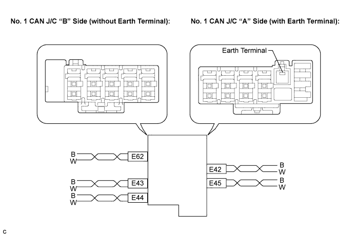

No. 1 CAN J/C Connector ("A" side, with earth terminal)
Connector Color
Wire Color (CAN-H)
Wire Color (CAN-L)
CAN Main Bus Wire (E42)
White
B
W
Center Airbag Sensor Assembly (E45)
Black
B
W
No. 1 CAN J/C Connector ("B" side, without earth terminal)
Connector Color
Wire Color (CAN-H)
Wire Color (CAN-L)
DLC3 (E62)
Gray
B
W
Combination Meter (E43)
White
B
W
Main Body ECU (E44)
Black
B
W
No. 4 CAN J/C (REAR OF THE VEHICLE)
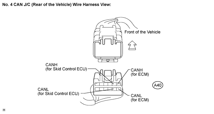
Terminal
Wiring Color
Destination
A40-1 (CANH)
B
ECM (CANH)
A40-7 (CANL)
W
ECM (CANL)
A40-2 (CANH)
B
Skid Control ECU (CANH)
A40-8 (CANL)
W
Skid Control ECU (CANL)
No. 4 CAN J/C (FRONT OF THE VEHICLE)
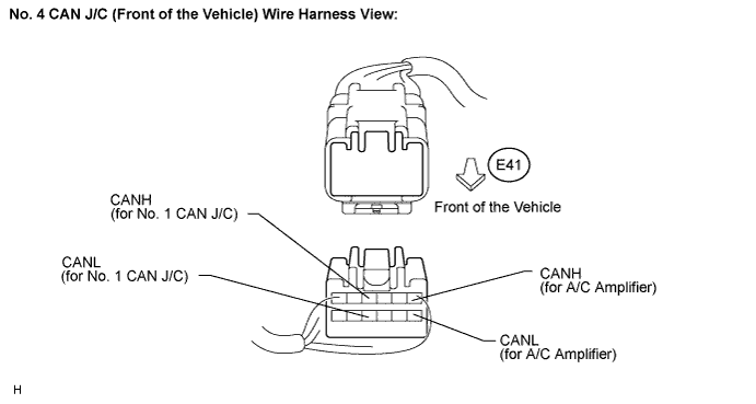
Terminal
Wiring Color
Destination
E41-1 (CANH)
B
A/C Amplifier (CANH)
E41-7 (CANL)
W
A/C Amplifier (CANL)
E41-4 (CANH)
B
No. 1 CAN J/C (CANH)
E41-10 (CANL)
W
No. 1 CAN J/C (CANL)
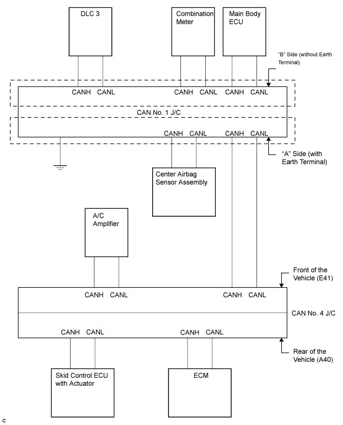
The connection diagram of the components which are connected to the CAN J/C
| DLC3 |
Measure the resistance according to the value(s) in the table below.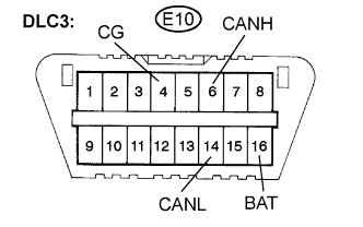
- Standard resistance:
Terminals
Wiring Color
Terminal Description
Condition
Specified Condition
E10-6 (CANH) - E10-14 (CANL)
B - W
HIGH-level CAN bus wire - LOW-level CAN bus wire
Ignition switch off
54 to 69 Ω
E10-6 (CANH) - E10-4 (CG)
B - W-B
HIGH-level CAN bus wire - Ground
Ignition switch off
200 Ω or higher
E10-14 (CANL) - E10-4 (CG)
W - W-B
LOW-level CAN bus wire - Ground
Ignition switch off
200 Ω or higher
E10-6 (CANH) - E10-16 (BAT)
B - L
HIGH-level CAN bus wire - Battery positive
Ignition switch off
6 kΩ or higher
E10-14 (CANL) - E10-16 (BAT)
W - L
LOW-level CAN bus wire - Battery positive
Ignition switch off
6 kΩ or higher
| SKID CONTROL ECU |
Disconnect the A25 skid control ECU connector.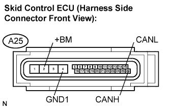
Measure the resistance according to the value(s) in the table below.
- Standard resistance:
Terminals
Wiring Color
Terminal Description
Condition
Specified Condition
A25-26 (CANH) - A25-15 (CANL)
B - W
HIGH-level CAN bus wire - LOW-level CAN bus wire
Ignition switch off
54 to 69 Ω
A25-26 (CANH) - A25-4 (GND1)
B - W-B
HIGH-level CAN bus wire - Ground
Ignition switch off
200 Ω or higher
A25-15 (CANL) - A25-4 (GND1)
W - W-B
LOW-level CAN bus wire - Ground
Ignition switch off
200 Ω or higher
A25-26 (CANH) - A25-3 (+BS)
B - L
HIGH-level CAN bus wire - Battery positive
Ignition switch off
6 kΩ or higher
A25-15 (CANL) - A25-3 (+BS)
W - L
LOW-level CAN bus wire - Battery positive
Ignition switch off
6 kΩ or higher
| CENTER AIRBAG SENSOR ASSEMBLY |
Disconnect the E30 center airbag sensor assembly connector.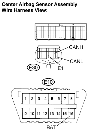
Measure the resistance according to the value(s) in the table below.
- Standard resistance:
Terminals
Wiring Color
Terminal Description
Condition
Specified Condition
E30-13 (CANH) - E30-22 (CANL)
B - W
HIGH-level CAN bus wire - LOW-level CAN bus wire
Ignition switch off
54 to 69 Ω
E30-13 (CANH) - E30-25 (E1)
B - W-B
HIGH-level CAN bus wire - Ground
Ignition switch off
200 Ω or higher
E30-22 (CANL) - E30-25 (E1)
W - W-B
LOW-level CAN bus wire - Ground
Ignition switch off
200 Ω or higher
E30-13 (CANH) - E10-16 (BAT)
B - L
HIGH-level CAN bus wire - Battery positive
Ignition switch off
6 kΩ or higher
E30-22 (CANL) - E10-16 (BAT)
W - L
LOW-level CAN bus wire - Battery positive
Ignition switch off
6 kΩ or higher
| ECM |
Disconnect the A24 ECM connector.
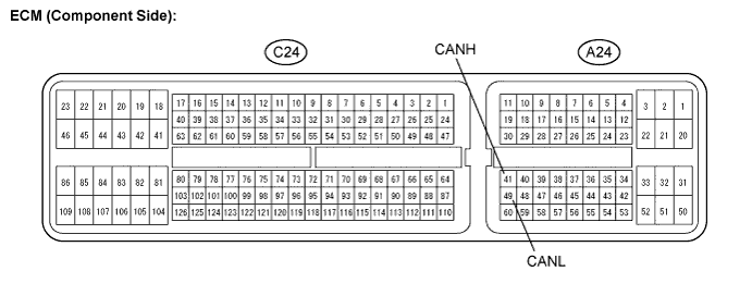
Disconnect the A24 and C24 ECM connectors.
Measure the resistance according to the value(s) in the table below.
- Standard resistance:
Terminals
Condition
Specified Condition
A24-41 (CANH) - A29-49 (CANL)
Ignition switch off
108 to 132 Ω
Measure the resistance according to the value(s) in the table below.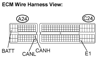
- Standard resistance:
Terminals
Wiring Color
Terminal Description
Condition
Specified Condition
A24-41 (CANH) - A24-49 (CANL)
B - W
HIGH-level CAN bus wire - LOW-level CAN bus wire
Ignition switch off
108 to 132 Ω
A24-41 (CANH) - C24-104 (E1)
B - W-B
HIGH-level CAN bus wire - Ground
Ignition switch off
200 Ω or higher
A24-49 (CANL) - C24-104 (E1)
W - W-B
LOW-level CAN bus wire - Ground
Ignition switch off
200 Ω or higher
A24-41 (CANH) - A24-20 (BATT)
B - Y
HIGH-level CAN bus wire - Battery positive
Ignition switch off
6 kΩ or higher
A24-49 (CANL) - A24-20 (BATT)
W - Y
LOW-level CAN bus wire - Battery positive
Ignition switch off
6 kΩ or higher
| AIR CONDITIONING AMPLIFIER |
Check the harness side connector (E38) of the air conditioning amplifier.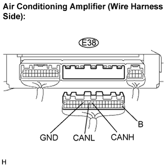
Disconnect the connector (E38) from the air conditioning amplifier.
Measure the resistance according to the value(s) in the table below.
- Standard resistance:
Terminals
Wiring Color
Terminal Description
Condition
Specified Condition
E38-11 (CANH) - E38-12 (CANL)
B - W
HIGH-level CAN bus wire - LOW-level CAN bus wire
Ignition switch off
54 to 69 Ω
E38-11 (CANH) - E38-14 (GND)
B - W-B
HIGH-level CAN bus wire - Ground
Ignition switch off
200 Ω or higher
E38-12 (CANL) - E38-14 (GND)
W - W-B
LOW-level CAN bus wire - Ground
Ignition switch off
200 Ω or higher
E38-11 (CANH) - E38-21 (B)
B - GR
HIGH-level CAN bus wire - Battery positive
Ignition switch off
6 kΩ or higher
E38-12 (CANL) - E38-21 (B)
W - GR
LOW-level CAN bus wire - Battery positive
Ignition switch off
6 kΩ or higher
| COMBINATION METER |
Disconnect the F1 combination meter connector.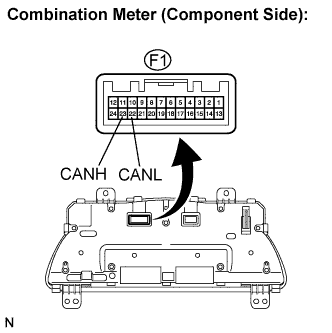
Measure the resistance according to the value(s) in the table below.
- Standard resistance:
Terminals
Condition
Specified Condition
F1-23 (CANH) - F1-22 (CANL)
Ignition switch off
108 to 132 Ω
Measure the resistance according to the value(s) in the table below.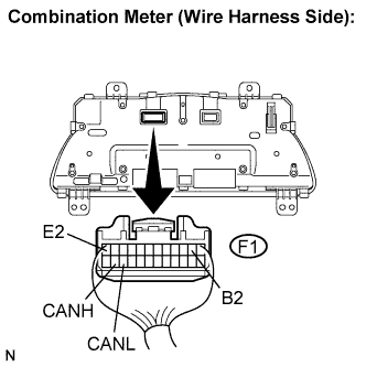
- Standard resistance:
Terminals
Wiring Color
Terminal Description
Condition
Specified Condition
F1-23 (CANH) - F1-22 (CANL)
B - W
HIGH-level CAN bus wire - LOW-level CAN bus wire
Ignition switch off
108 to 132 Ω
F1-23 (CANH) - F1-12 (E2)
B - W-B
HIGH-level CAN bus wire - Ground
Ignition switch off
200 Ω or higher
F1-22 (CANL) - F1-12 (E2)
W - W-B
LOW-level CAN bus wire - Ground
Ignition switch off
200 Ω or higher
F1-23 (CANH) - F1-2 (B2)
B - R
HIGH-level CAN bus wire - Battery positive
Ignition switch off
6 kΩ or higher
F1-22 (CANL) - F1-2 (B2)
W - R
LOW-level CAN bus wire - Battery positive
Ignition switch off
6 kΩ or higher
| MAIN BODY ECU (INSTRUMENT PANEL J/B) |
Disconnect the E8 main body ECU connector.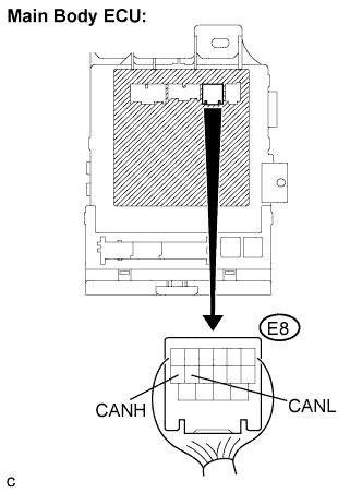
Measure the resistance according to the value(s) in the table below.
- Standard resistance:
Terminals
Wiring Color
Terminal Description
Condition
Specified Condition
E8-5 (CANH) - E8-6 (CANL)
B - W
HIGH-level CAN bus wire - LOW-level CAN bus wire
Ignition switch off
54 to 69 Ω