TERMINALS OF ECU
System information · Vehicles built Oct 2006 – May 2009
Versions by build date: Jun 2006 – Sep 2006 Oct 2006 – May 2009 from Jun 2009
| NAVIGATION RECEIVER ASSEMBLY |
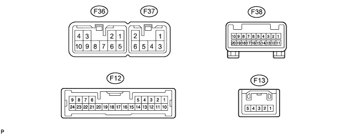

| Symbols (Terminal No.) |
Wiring Color |
Terminal Description |
Condition |
Specification |
| SPD (F13-3) - GND (F36-7) |
V - BR |
Speed signal from combination meter (for navigation function) |
See "Vehicle Signal Check" (Click here) |
- |
| REV (F13-5) - GND (F36-7) |
R - BR |
Reverse signal |
See "Vehicle Signal Check" (Click here) |
- |
| FR+ (F36-1) - GND (F36-7) |
LG - BR |
Sound signal (Front Right) |
Audio system is playing |
A waveform synchronized with sounds is output |
| FL+ (F36-2) - GND (F36-7) |
P - BR |
Sound signal (Front Left) |
Audio system is playing |
A waveform synchronized with sounds is output |
| ACC (F36-3) - GND (F36-7) |
GR - BR |
Accessory (ON) |
Ignition switch off → on (ACC) |
Below 1 V → 10 to 14 V |
| B (F36-4) - GND (F36-7) |
L-Y - BR |
Battery |
Always |
10 to 14 V |
| FR- (F36-5) - GND (F36-7) |
L - BR |
Sound signal (Front Right) |
Audio system is playing |
A waveform synchronized with sounds is output |
| FL- (F36-6) - GND (F36-7) |
V - BR |
Sound signal (Front Left) |
Audio system is playing |
A waveform synchronized with sounds is output |
| GND (F36-7) - Body ground |
BR - Body ground |
Ground |
Always |
Below 1 V |
| ANT (F36-8) - GND (F36-7) |
O - BR |
Power source of antenna |
Ignition switch on (IG) Radio switch ON and AM or FM selected |
10 to 14 V |
| ILL+ (F36-10) - GND (F36-7) |
G - BR |
Illumination signal |
Light control switch off → tail or head |
Below 1 V → 10 to 14 V |
| RR+ (F37-1) - GND (F36-7) |
R - BR |
Sound signal (Rear Right) |
Audio system is playing |
A waveform synchronized with sounds is output |
| RL+ (F37-2) - GND (F36-7) |
B - BR |
Sound signal (Rear Left) |
Audio system is playing |
A waveform synchronized with sounds is output |
| RR- (F37-3) - GND (F36-7) |
W - BR |
Sound signal (Rear Right) |
Audio system is playing |
A waveform synchronized with sounds is output |
| RL- (F37-6) - GND (F36-7) |
Y - BR |
Sound signal (Rear Left) |
Audio system is playing |
A waveform synchronized with sounds is output |
| SWG (F38-6) - Body ground |
P - Body ground |
Steering pad switch ground |
Always |
Below 1 V |
| SW1 (F38-7) - SWG (F38-6) |
O - P |
Steering pad switch signal |
No switch is pushed → SEEK+ switch pushed → SEEK- switch pushed → VOL+ switch pushed → VOL- switch pushed |
4 V or higher → Approx. 0.5 V → Approx. 0.9 V → Approx. 2.0 V → Approx. 3.4 V |
| SW2 (F38-8) - SWG (F38-6) |
Y - P |
Steering pad switch signal |
No switch is pushed → MODE switch pushed → ON HOOK switch pushed → OFF HOOK switch pushed → VOICE switch pushed |
4 V or higher → Approx. 0.5 V → Approx. 0.9 V → Approx. 2.0 V → Approx. 3.4 V |
| MUTE (F12-6) - GND (F36-7) (*1) |
GR - BR |
Mute signal |
TOYOTA link system operating → Source is changed |
Above 3.5 V → Below 1 V |
| TSW- (F12-12) - GND (F36-7) |
P - BR |
Telephone relation switch signal |
Always |
Below 1 V |
| MACC (F12-17) - GND (F36-7) |
LG - BR |
Microphone AMP power supply |
Ignition switch off → on (IG) |
Below 1 V → 5 V |
| SGND (F12-18) - GND (F36-7) |
P - BR |
Ground |
Always |
Below 1 V |
| MIC+ (F12-19) - GND (F36-7) |
G - BR |
Microphone voice signal |
See "Microphone Check" (Click here) |
- |
| MIC- (F12-20) - Body ground |
R - Body ground |
Microphone voice signal |
See "Microphone Check" (Click here) |
- |
| CGND (F12-21) - GND (F36-7) |
W - BR |
Ground |
Always |
Below 1 V |
| V+ (F12-22) - GND (F36-7) |
R - BR |
Television camera image signal |
Ignition switch on (IG), shift lever in R |
Pulse generation (Refer to waveform 1) |
| V- (F12-23) - CGND (F12-21) |
Shielded - W |
Shielded ground |
Always |
Below 1 V |
| CA+ (F12-24) - GND (F36-7) |
B - BR |
Television camera power supply |
Ignition switch on (IG), shift lever in R |
Approx. 6 V |
- *1: with TOYOTA Link System
Reference: waveform 1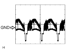
- HINT:
- Terminal: V+ - CGND
- Gauge set: 0.2 V/DIV., 0.2 μs/DIV.
- Condition: Ignition switch on (IG), shift lever in R
- Terminal: V+ - CGND
| MAYDAY ECU (with TOYOTA Link System) (Click here) |