Door Courtesy Switch Circuit
Circuit diagnosis · Vehicles built from Oct 2006
DESCRIPTION
The main body ECU detects the condition of the door courtesy switches.- HINT:
- The main body ECU receives driver side, passenger side, rear LH, and rear RH door courtesy switch signals to control the illuminated entry system.
- The main body ECU receives driver side, passenger side, rear LH, and rear RH door courtesy switch signals to control the illuminated entry system.
- The main body ECU receives driver side, passenger side, rear LH, rear RH, and luggage compartment door courtesy switch signals to control the light auto turn off system.
- The main body ECU receives driver side, passenger side, rear LH, rear RH, and luggage compartment door courtesy switch signals to control the light auto turn off system.
- When performing troubleshooting, inspect the switch that is related to the malfunction only. For example, if the illuminated entry system does not operate when opening the passenger side door with the ignition switch off, inspect the passenger side door courtesy switch circuit only.
- When performing troubleshooting, inspect the switch that is related to the malfunction only. For example, if the illuminated entry system does not operate when opening the passenger side door with the ignition switch off, inspect the passenger side door courtesy switch circuit only.
WIRING DIAGRAM
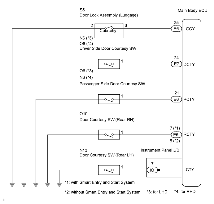

INSPECTION PROCEDURE
| 1. READ VALUE USING INTELLIGENT TESTER |

Connect the intelligent tester to the DLC3.
Turn the ignition switch on (IG) and turn the intelligent tester main switch on.
Select the items below in the DATA LIST, and read the display on the intelligent tester.
Main Body (Main Body ECU): Tester Display
Measurement Item/Range
Normal Condition
Diagnostic Note
D Door Courtesy SW
Driver side door courtesy switch signal / ON or OFF
ON: Driver side door is open
OFF: Driver side door is closed
-
P Door Courtesy SW
Passenger side door courtesy switch signal / ON or OFF
ON: Passenger side door is open
OFF: Passenger side door is closed
-
RR Door Courtesy SW
Rear right door courtesy switch signal / ON or OFF
ON: Rear right door is open
OFF: Rear right door is closed
-
RL Door Courtesy SW
Rear left door courtesy switch signal / ON or OFF
ON: Rear left door is open
OFF: Rear left door is closed
-
Luggage Courtesy SW
Luggage compartment door courtesy switch signal / ON or OFF
ON: Luggage compartment door is open
OFF: Luggage compartment door is closed
-
- OK:
- Normal conditions listed above are displayed.
|
|
||||

| NG | |
 |
| 2. INSPECT DOOR COURTESY SWITCH |
Inspect the front door courtesy switch (Click here), rear door courtesy switch (Click here), or luggage compartment door courtesy switch (Click here).
- OK:
- Door courtesy switches are normal.
|
|
||||
| OK | |
|
| 3. CHECK HARNESS AND CONNECTOR (MAIN BODY ECU - DOOR COURTESY SWITCH) |
Check the harness and connector between the main body ECU and door courtesy switches (passenger side and rear RH).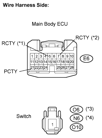
Disconnect the E6 main body ECU connector.
Disconnect the O6*3 or N6*4 switch connectors.
Disconnect the O10 switch connectors.
Measure the resistance according to the value(s) in the table below.
- Standard resistance:
Tester Connection
Condition
Specified Condition
E6-5 (*1) - O10-1 (Rear RH)
Always
Below 1 Ω
E6-7 (*2) - O10-1 (Rear RH)
Always
Below 1 Ω
E6-21 (PCTY) - O6-1*3 (Front passenger side)
Always
Below 1 Ω
E6-21 (PCTY) - N6-1*4 (Front passenger side)
Always
Below 1 Ω
O10-1 (Rear RH) - Body ground
Always
10 kΩ or higher
O6-1*3 (Front passenger side) - Body ground
Always
10 kΩ or higher
N6-1*4 (Front passenger side) - Body ground
Always
10 kΩ or higher
- HINT:
- *1: without Smart Entry and Start System
- *2: with Smart Entry and Start System
- *3: for LHD
- *4: for RHD
Check the harness and connector between the instrument panel J/B assembly and rear LH door courtesy switch.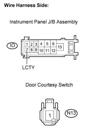
Disconnect the IO instrument panel J/B assembly connector.
Disconnect the N13 switch connector.
Measure the resistance according to the value(s) in the table below.
- Standard resistance:
Tester Connection
Condition
Specified Condition
IO-7 (LCTY) - N13-1 (Rear LH)
Always
Below 1 Ω
IO-7 (LCTY) - Body ground
Always
10 kΩ or higher
Check the harness and connector between the main body ECU and driver side door courtesy switch.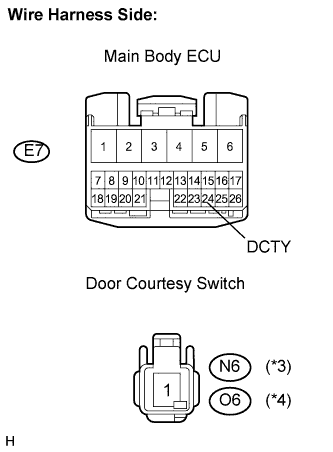
Disconnect the E7 main body ECU connector.
Disconnect the N6*3 or O6*4 switch connector.
Measure the resistance according to the value(s) in the table below.
- Standard resistance:
Tester Connection
Condition
Specified Condition
E7-24 (DCTY) - N6-1*3 (Driver side)
Always
Below 1 Ω
E7-24 (DCTY) - O6-1*4 (Driver side)
Always
Below 1 Ω
E7-24 (DCTY) - Body ground
Always
10 kΩ or higher
- HINT:
- *3: for LHD
- *4: for RHD
Check the harness and connector between the main body ECU and luggage compartment door courtesy switch.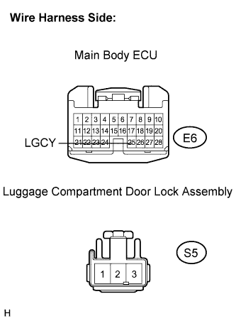
Disconnect the E6 main body ECU connector.
Disconnect the S5 switch connector.
Measure the resistance according to the value(s) in the table below.
- Standard resistance:
Tester Connection
Condition
Specified Condition
E6-25 (LGCY) - S5-3 (Driver side)
Always
Below 1 Ω
E6-25 (LGCY) - Body ground
Always
10 kΩ or higher
S5-2 - Body ground
Always
Below 1 Ω
|
|
||||
| OK | ||
 |
||
| ||