Rear Door UNLOCK Detection Switch LH Circuit
Circuit diagnosis · Vehicles built from Jun 2009
Versions by build date: Jun 2006 – May 2009 from Jun 2009
DESCRIPTION
The rear left door unlock detection switch is built into the rear left door lock assembly. The switch turns on when the rear left door is unlocked and turns off when the door is locked.The main body ECU is connected to the rear left door lock assembly via terminal LSWP (*1) or LSWL (*2) and rear left door lock/unlock state signals are input to the ECU.
The main body ECU applies voltage to the door unlock detection switch via terminal LSWP (*1) or LSWL (*2). When the door unlock detection switch is on (there is continuity between the switch terminals), an unlock state signal is input to the ECU. When the switch is off (there is no continuity between the switch terminals), a lock state signal is input.
- *1: without Smart Entry and Start System
- *2: with Smart Entry and Start System
WIRING DIAGRAM
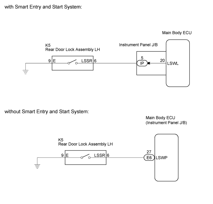

INSPECTION PROCEDURE
| 1. SYSTEM CHECK |

Check the vehicle specification.
- Result:
Result
Proceed to
with Smart Entry and Start System
A
without Smart Entry and Start System
B
|
|
||||

| A | |
 |
| 2. READ VALUE USING INTELLIGENT TESTER |
Connect the intelligent tester to the DLC3.
Turn the ignition switch on (IG).
Turn the intelligent tester on.
Enter the following menus: Body / Main Body / Data List.
Read the Data List according to the display on the intelligent tester.
Main Body Tester Display
Measurement Item/Range
Normal Condition
Diagnostic Note
RL-Door Lock Pos SW
Rear left door lock position switch signal/ON or OFF
ON: Rear left door lock is in UNLOCK position
OFF: Rear left door lock is in LOCK position
-
- OK:
- On the intelligent tester screen, the item changes between ON and OFF according to the chart above.
|
|
||||
| OK | ||
 |
||
| ||
| 3. INSPECT REAR DOOR LOCK ASSEMBLY (UNLOCK DETECTION SWITCH) |
Remove the rear door lock assembly LH.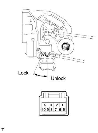
Measure the resistance according to the value(s) in the table below.
- Standard resistance:
Tester Connection
Measurement Condition
Door Lock Condition
Specified Condition
6 - 9
Battery positive (+) → Terminal 4
Battery negative (-) → Terminal 1
Locked
10 kΩ or higher
6 - 9
Battery positive (+) → Terminal 1
Battery negative (-) → Terminal 4
Unlocked
Below 1 Ω
|
|
||||

| OK | |
|
| 4. CHECK WIRE HARNESS (REAR DOOR LOCK - MAIN BODY ECU (INSTRUMENT PANEL J/B)) |
Disconnect the rear door lock assembly LH connector.
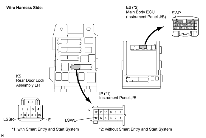
Disconnect the instrument panel J/B (*1) or main body ECU (*2) connector.
- *1: with Smart Entry and Start System
- *2: without Smart Entry and Start System
- *1: with Smart Entry and Start System
Measure the resistance according to the value(s) in the table below.
- Standard resistance:
with Smart Entry and Start System Tester Connection
(Symbols)
Condition
Specified Condition
K5-6 (LSSR) - IP-5 (LSWL)
Always
Below 1 Ω
K5-6 (LSSR) - Body ground
Always
10 kΩ or higher
K5-9 (E) - Body ground
Always
Below 1 Ω
- Standard resistance:
without Smart Entry and Start System Tester Connection
(Symbols)
Condition
Specified Condition
K5-6 (LSSR) - E6-27 (LSWP)
Always
Below 1 Ω
K5-6 (LSSR) - Body ground
Always
10 kΩ or higher
K5-9 (E) - Body ground
Always
Below 1 Ω
|
|
||||
| OK | ||
|
||
| ||