2006-2011 Camry Aurion · Service Manual BRAKE

TC and CG Terminal Circuit

Circuit diagnosis · Vehicles built from Jun 2009

Versions by build date: Jun 2006 – Sep 2006 Oct 2006 – May 2009 from Jun 2009

DESCRIPTION

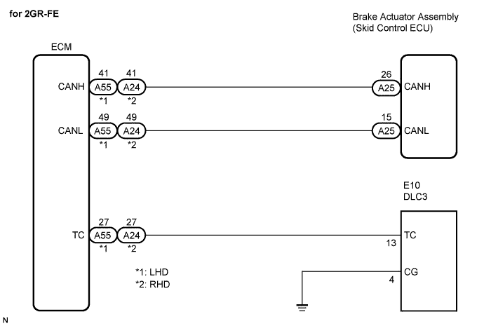
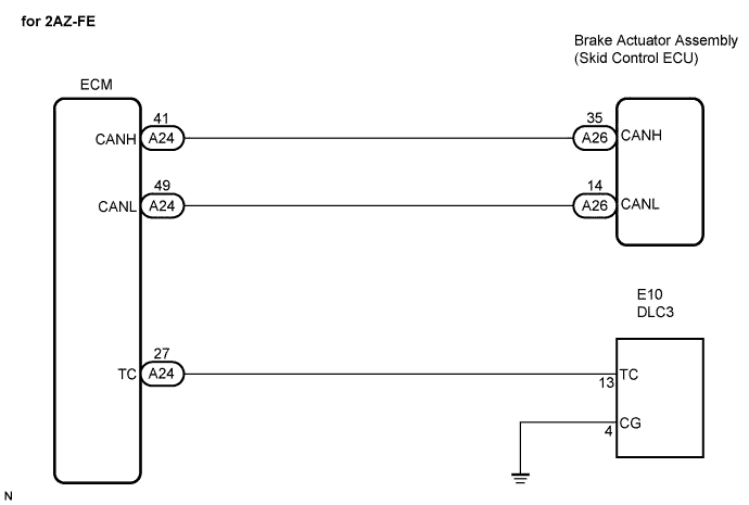
DTC output mode is set by connecting terminals TC and CG of the DLC3.
DTCs are indicated by the blinking pattern of the ABS warning light.

WIRING DIAGRAM

C141358E07
C136513E05

HINT:
When the warning lights continue to blink, a ground short in the wiring of terminal TC of the DLC3 or an internal ground short in one or more ECUs is suspected.


INSPECTION PROCEDURE

HINT:
Check the condition of each related circuit connector before troubleshooting (Click here).


1. CHECK CAN COMMUNICATION SYSTEM
  1. Check if a CAN communication DTC is output (Click here).
    Result:
    Result
    Proceed to
    CAN communication system DTC is output
    A
    CAN communication system DTC is not output
    B


B
Go to step 2
A

GO TO CAN COMMUNICATION SYSTEM (Click here)

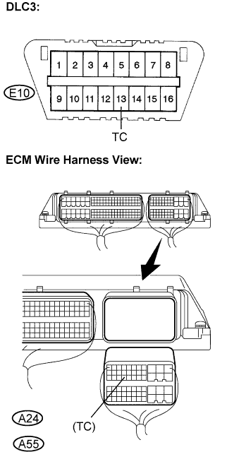
2. CHECK HARNESS AND CONNECTOR (ECM TO DLC3)

  1. C136035E10
    Disconnect the ECM connector.

  1. Measure the resistance according to the value(s) in the table below.

    Standard resistance:
    for 2AZ-FE:
    Tester Connection
    Specified Condition
    E10-13 (TC) - A24-27 (TC)
    Below 1 Ω
    E10-13 (TC) - Body ground
    10 kΩ or higher

    Standard resistance:
    for 2GR-FE:
    Tester Connection
    Specified Condition
    E10-13 (TC) - A55-27 (TC): LHD
    Below 1 Ω
    E10-13 (TC) - A24-27 (TC): RHD
    Below 1 Ω
    E10-13 (TC) - Body ground
    10 kΩ or higher

  1. Connect the connector.


NG
REPAIR OR REPLACE HARNESS OR CONNECTOR (TC TERMINAL CIRCUIT)
OK


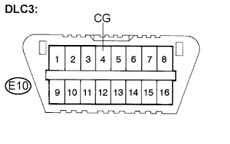
3. CHECK HARNESS AND CONNECTOR (DLC3 CG CIRCUIT)

  1. G022986E27
    Measure the resistance according to the value(s) in the table below.

    Standard resistance:
    Tester Connection
    Specified Condition
    E10-4 (CG) - Body ground
    Below 1 Ω


NG
REPAIR OR REPLACE HARNESS OR CONNECTOR (CG TERMINAL CIRCUIT)
OK


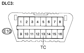
4. CHECK HARNESS AND CONNECTOR (TC TERMINAL CIRCUIT)

  1. G022986E28
    Measure the resistance according to the value(s) in the table below.

    Standard resistance:
    Tester Connection
    Specified Condition
    E10-13 (TC) - Body ground
    10 kΩ or higher


NG
REPAIR OR REPLACE HARNESS OR CONNECTOR (TC TERMINAL CIRCUIT)
OK

REPLACE BRAKE ACTUATOR ASSEMBLY (Click here)


← TC and CG Terminal Circuit (Oct 2006 – May 2009)TS and CG Terminal Circuit (from Jun 2006) →