Wireless Door Lock Buzzer Circuit
Circuit diagnosis · Vehicles built from Jun 2006
DESCRIPTION
The main body ECU activates the wireless door lock buzzer when detecting a lock/unlock signal from the door control transmitter.WIRING DIAGRAM
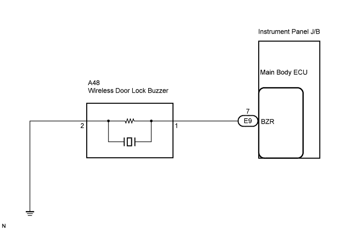

INSPECTION PROCEDURE
| 1. INSPECT WIRELESS DOOR LOCK BUZZER |

Disconnect the A48 wireless door lock buzzer connector.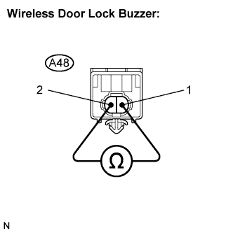
Measure the resistance according to the value(s) in the table below.
- HINT:
- The buzzer activation circuit is built into the ECU, not into the buzzer itself. When battery voltage is applied directly to the buzzer, the buzzer will not sound.
- Standard resistance:
Tester Connection
Condition
Specified Condition
A48-1 - A48-2
Always
Approx. 1 kΩ
|
|
||||

| OK | |
 |
| 2. CHECK HARNESS AND CONNECTOR (MAIN BODY ECU - WIRELESS DOOR LOCK BUZZER - BODY GROUND) |
Disconnect the E9 main body ECU connector.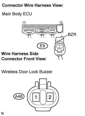
Measure the resistance according to the value(s) in the table below.
- Standard resistance:
Symbol
(Tester Connection)
Condition
Specified Condition
BZR (E9-7) - A48-1
Always
Below 1 Ω
BZR (E9-7) - Body ground
Always
10 kΩ or higher
A48-1 - Body ground
Always
10 kΩ or higher
A48-2 - Body ground
Always
Below 1 Ω
|
|
||||
| OK | ||
 |
||
| ||