B1242 Wireless Door Lock Tuner Circuit Malfunction
Diagnostic trouble codes · Vehicles built from Jun 2009
Versions by build date: Jun 2006 – Sep 2006 Oct 2006 – May 2009 from Jun 2009
DESCRIPTION
The door control receiver receives signals from the transmitter and sends these signals to the main body ECU.| DTC No. |
DTC Detection Condition |
Trouble Area |
| B1242 |
In diagnostic mode, an applicable RDA signal cannot be received within 1 second after an PRG signal has been output from the main body ECU. |
|
WIRING DIAGRAM
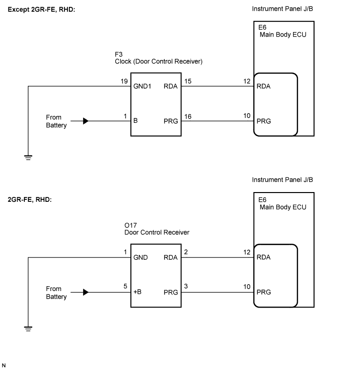

INSPECTION PROCEDURE
| 1. CHECK DOOR CONTROL RECEIVER |

Choose the door control receiver to be inspected.
Apparatus
Proceed to
Except for 2GR-FE, RHD
A
2GE-FE, RHD
B
|
|
||||

| A | |
 |
| 2. CHECK HARNESS AND CONNECTOR (MAIN BODY ECU - DOOR CONTROL RECEIVER) |
Disconnect the E6 main body ECU connector and the F3 door control receiver connector.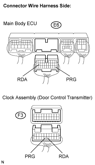
Measure the resistance according to the value(s) in the table below.
- Standard resistance:
Symbol
(Tester Connection)
Condition
Specified Condition
RDA (E6-12) - RDA (F3-15)
Always
Below 1 Ω
RDA (E6-12) - Body ground
Always
10 kΩ or higher
PRG (E6-10) - PRG (F3-16)
Always
Below 1 Ω
PRG (E6-10) - Body ground
Always
10 kΩ or higher
|
|
||||

| OK | |
|
| 3. CHECK HARNESS AND CONNECTOR (BATTERY, BODY GROUND) |
Measure the voltage and resistance according to the value(s) in the table below.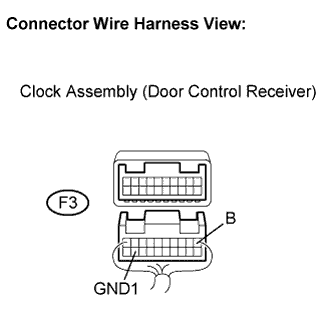
- Standard:
Symbol
(Tester Connection)
Condition
Specified Condition
GND1 (F3-19) - Body ground
Always
Below 1 Ω
B (F3-1) - Body ground
Always
10 to 14 V
|
|
||||
| OK | |
|
| 4. REPLACE CLOCK ASSEMBLY (DOOR CONTROL RECEIVER) |
Reconnect the E6 main body ECU connector.
Replace the clock assembly (door control receiver) with a normal one.
Perform the registration procedures (Click here).
- HINT:
- If a normally functioning door control receiver is available, connect it and check if the wireless door lock function is normal or DTCs are output. If the alternative receiver functions normally, replace the original door control receiver.
| NEXT | |
|
| 5. CONFIRM DTC |
Clear the DTCs (Click here).
Check if the same DTC is detected.
- HINT:
- Reinstall the sensors, connectors, etc. and restore the previous vehicle conditions before rechecking for DTCs.
- Result:
Result
Proceed to
DTC is output
A
DTC is not output
B
|
|
||||
| A | ||
 |
||
| ||
| 6. CHECK HARNESS AND CONNECTOR (MAIN BODY ECU - DOOR CONTROL RECEIVER) |
Disconnect the E6 main body ECU connector and the O17 door control receiver connector.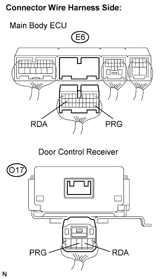
Measure the resistance according to the value(s) in the table below.
- Standard resistance:
Symbol
(Tester Connection)
Condition
Specified Condition
RDA (E6-12) - RDA (O17-2)
Always
Below 1 Ω
RDA (E6-12) - Body ground
Always
10 kΩ or higher
PRG (E6-10) - PRG (O17-3)
Always
Below 1 Ω
PRG (E6-10) - Body ground
Always
10 kΩ or higher
|
|
||||
| OK | |
|
| 7. CHECK HARNESS AND CONNECTOR (BATTERY, BODY GROUND) |
Measure the voltage and resistance according to the value(s) in the table below.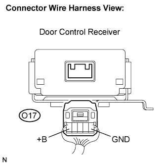
- Standard:
Symbol
(Tester Connection)
Condition
Specified Condition
GND (O17-1) - Body ground
Always
Below 1 Ω
+B (O17-5) - Body ground
Always
10 to 14 V
|
|
||||
| OK | |
|
| 8. REPLACE DOOR CONTROL RECEIVER |
Reconnect the E6 main body ECU connector.
Replace the door control receiver with a normal one.
Perform the registration procedures (Click here).
- HINT:
- If a normally functioning door control receiver is available, connect it and check if the wireless door lock function is normal or DTCs are output. If the alternative receiver functions normally, replace the original door control receiver.
| NEXT | |
|
| 9. CONFIRM DTC |
Clear the DTCs (Click here).
Check if the same DTC is detected.
- HINT:
- Reinstall the sensors, connectors, etc. and restore the previous vehicle conditions before rechecking for DTCs.
- Result:
Result
Proceed to
DTC is output
A
DTC is not output
B
|
|
||||
| A | ||
|
||
| ||