TERMINALS OF ECU
System information · Vehicles built from Oct 2006
| CHECK MAIN BODY ECU (INSTRUMENT PANEL J/B) |
Disconnect the main body ECU (instrument panel J/B) connectors.
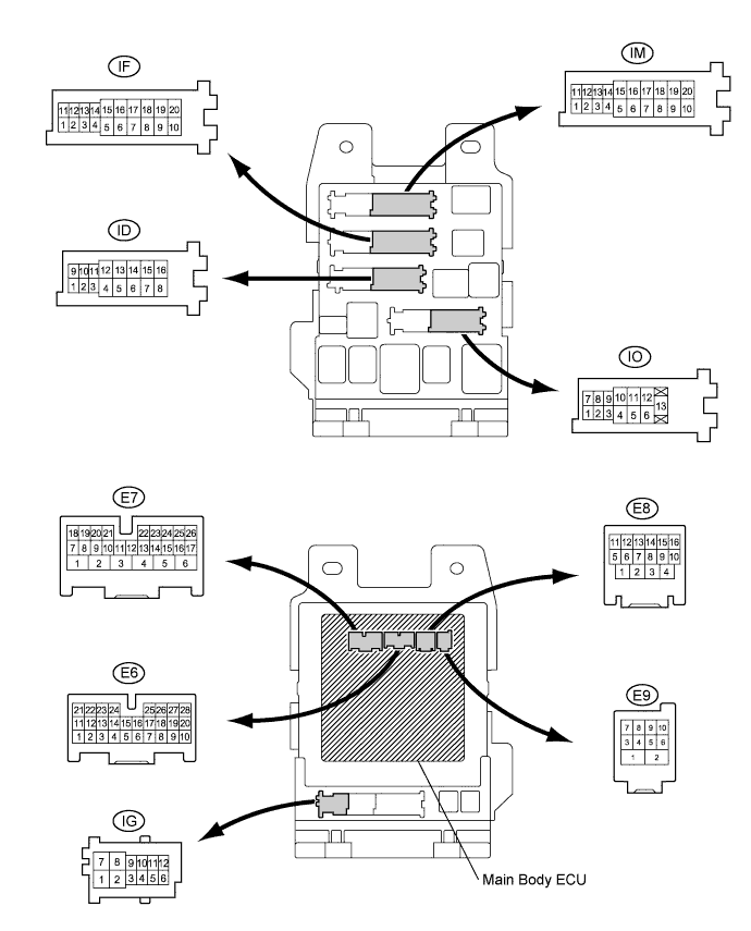

Measure the resistance and voltage between each terminal of the wire harness side connectors and body ground.
If the result is not as specified, there may be a malfunction on the wire harness side.Symbols (Terminal No.)
Wiring Color
Terminal Description
Condition
Specified Condition
RCTY (E6-7) - Body ground
GR - Body ground
Rear courtesy light switch RH input
Rear door RH CLOSED (OFF) → OPEN (ON)
10 kΩ or higher → Below 1 Ω
PCTY (E6-21) - Body ground
L - Body ground
Passenger side courtesy light switch input
Passenger side door CLOSED (OFF) → OPEN (ON)
10 kΩ or higher → Below 1 Ω
LGCY (E6-25) - Body ground
W - Body ground
Luggage compartment door courtesy light switch input
Luggage compartment door CLOSED (OFF) → OPEN (ON)
10 kΩ or higher → Below 1 Ω
DCTY (E7-24) - Body ground
Y - Body ground
Driver side door courtesy light switch input
Driver side door CLOSED (OFF) → OPEN (ON)
10 kΩ or higher → Below 1 Ω
ACC (IF-2) - Body ground
L - Body ground
Ignition power supply (ACC signal)
Engine switch on (ACC) → off
10 to 14 V → Below 1 V
IG (IF-11) - Body ground
B - Body ground
Ignition power supply (IG signal)
Engine switch on (IG) → off
10 to 14 V → Below 1 V
ALTB (ID-16) - Body ground
W - Body ground
+B (power system alternator system) power supply
Always
10 to 14 V
GND1 (IF-10) - Body ground
W-B - Body ground
Ground
Always
Below 1 Ω
GND2 (IM-9) - Body ground
W-B - Body ground
Ground
Always
Below 1 Ω
LCTY (IO-7) - Body ground
LG - Body ground
Rear courtesy light switch LH input
Rear door LH CLOSED (OFF) → OPEN (ON)
10 kΩ or higher → Below 1 Ω
Reconnect the main body ECU (instrument panel J/B) connectors.
Measure the voltage between each terminal of the wire harness side connectors and body ground.
If the result is not as specified, the ECU may have a malfunction.Symbols (Terminal No.)
Wiring Color
Terminal Description
Condition
Specified Condition
HAZ (E8-4) - Body ground
W - Body ground
Turn signal flasher relay signal
System is in alarm sounding state
Below 1 V
HORN (ID-11) - Body ground
B - Body ground
Vehicle horn drive
Vehicle horn is sounding
(Theft deterrent system is in alarm sounding state)
Pulse generation
(0 V ← → 12 V)
| CHECK CERTIFICATION ECU ASSEMBLY |
Disconnect the E58 and E59 ECU connectors.
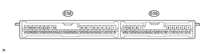
Measure the voltage and resistance of the wire harness side connector.
Symbols (Terminal No.)
Wiring Color
Terminal Description
Condition
Specified Condition
+B (E58-1) - E (E58-17)
W - W-B
Battery power supply
Always
10 to 14 V
E (E58-17) - Body ground
W-B - Body ground
Ground
Always
Below 1 Ω
HSW (E59-24) - Body ground
R - Body ground
Engine hood courtesy switch
Engine hood OPEN (OFF) → CLOSED (ON)
10 kΩ or higher → Below 1 Ω
- If the result is not as specified, there may be a malfunction on the wire harness side.
- If the result is not as specified, there may be a malfunction on the wire harness side.
Reconnect the E58 and E59 ECU connectors.
Measure the voltage of the connector.
Symbols (Terminal No.)
Wiring Color
Terminal Description
Condition
Specified Condition
IND (E58-2) - Body ground
Y - Body ground
Security indicator output
Security indicator is on
(It comes on only in arming preparation state or alarm sounding state. It flashes when immobiliser is operating.)
3 to 6 V
SH- (E59-20) - Body ground
P - Body ground
Security horn drive
Security horn is sounding
(Theft deterrent system is in alarm sounding state)
Pulse generation
(0 V ← → 12 V)
- If the result is not as specified, the ECU may have a malfunction.
- If the result is not as specified, the ECU may have a malfunction.