REASSEMBLY
Removal / installation · Vehicles built from Oct 2006
Versions by build date: Jun 2006 – Sep 2006 from Oct 2006
- NOTICE:
- When installing parts, coat the parts indicated by arrows with silicone grease (Click here).
| 1. INSTALL INNER RACK SEAL AND STEERING RACK |

Install the SST over the steering rack where the teeth are exposed.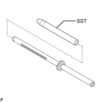

SST J46368
Lubricate the outside of the SST.
Remove the inner rack seal from the new inner rack seal insert.
Slide the inner rack seal over the SST and push the seal up against the piston.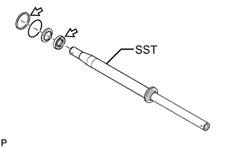
Remove the SST.
Lubricate the outside of the new inner rack seal insert.
Snap the inner rack seal insert onto the inner rack seal.
Install the new O-rings onto the piston. Lubricate the O-rings once installed.
Clean the inside of the rack and pinion housing assembly thoroughly.
Insert the small end of the SST into the housing assembly at the opposite end of the valve assembly.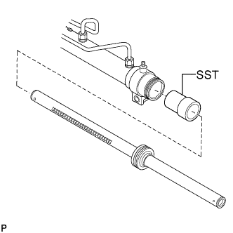
SST J46369
Install the steering rack into the housing assembly with the teeth facing the opening of the valve housing. Use enough force to fully install the steering rack into the housing assembly.
Remove the SST.
Place the housing assembly into a press with the valve end down.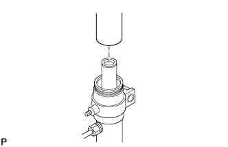
Use the press and a round steel stock to gently apply pressure to the steering rack until you feel a stop. Hold for 15 seconds and release.
| 2. INSTALL BULKHEAD AND SEALS ASSEMBLY |
Lubricate the bulkhead and seals assembly.
Insert the bulkhead and seals assembly into the rack and pinion housing assembly.
Insert the small end of the SST into the housing assembly at the opposite end of the valve assembly. Tap the SST with a rubber mallet until all parts seat against the shoulder inside the housing assembly.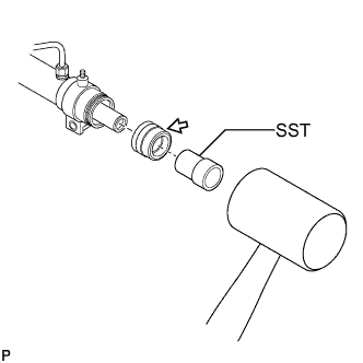
SST J46369
Remove the SST.
Install a new cylinder outer bulkhead assembly.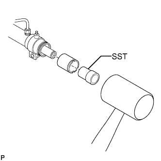
Insert the small end of the SST into the housing assembly at the opposite end of the valve assembly. Tap the SST with a rubber mallet until all parts seat against the shoulder inside the housing assembly.
SST J46369
Remove the SST.
Install the retaining ring onto the steering rack. Use the SST to push the retaining ring into the groove inside the housing assembly.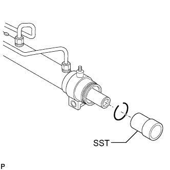
SST J46369
Remove the SST.
Check visually to ensure the retaining ring is snapped in place in the groove.
Clean the area around the drilled hole in the housing assembly and fill with silicone.
| 3. INSTALL PINION SHAFT SEAL |
Lubricate and install the pinion shaft seal.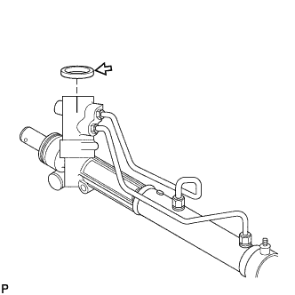
| 4. INSTALL PINION BEARING ASSEMBLY |
Remount the rack and pinion housing assembly in the vice, cylinder lines facing down.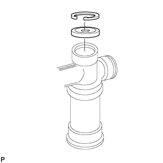
Install the pinion bearing assembly.
Install the retaining ring.
Remount the rack and pinion housing assembly in the vice, cylinder lines facing up
| 5. INSTALL VALVE BODY RINGS |
- NOTICE:
- Handle the pinion and valve assembly with caution. Failure to do so may result in replacement of the rack and pinion power steering gear assembly.
Lubricate the SST with power steering fluid.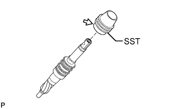
SST J46192-1
Install three upper valve body rings on the SST from the tapered end.
Use the SST to install the rings on the spool shaft.
Remove the SST.
Seat the valve body rings into grooves by hand.
Lubricate the SST with power steering fluid.
Install the lower valve body ring on the SST.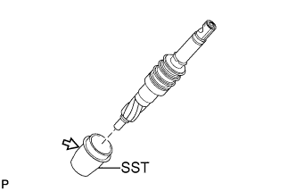
Use the SST to install the ring on the spool shaft.
Remove the SST.
Seat the valve body ring into groove by hand.
| 6. INSTALL PINION AND VALVE ASSEMBLY |
- NOTICE:
- Handle the pinion and valve assembly with caution. Failure to do so may result in replacement of the rack and pinion power steering gear assembly.
Lubricate inside of the SST with power steering fluid.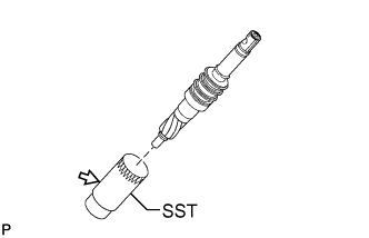
SST J46192-2
Slide the SST over the spool shaft to compress the valve body rings. Let it stand for two minutes. Clean inside the valve housing with lint free cloth.
- NOTICE:
- Do not hit spool shaft on hard surface.
Align the rack assembly using the marks inside the rack and pinion housing assembly.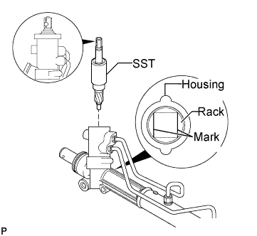
- NOTICE:
- The rack assembly must be aligned before installing the valve assembly. Failure to do so will cause the steering wheel to be out of position.
With the SST still on the valve assembly, install the valve assembly into the housing assembly.
- NOTICE:
- The orientation of the pinch bolt notch on the valve assembly must be aligned as shown. Failure to do so will cause the steering wheel to be out of position.
Remove the SST from the housing assembly.
Install the new needle bearing assembly onto the spool shaft of the valve assembly.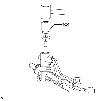
- NOTICE:
- The bearings in the needle bearing assembly must be facing down when installing into housing assembly.
Using the smaller end of the SST and a rubber mallet, gently tap the needle bearing assembly into the housing assembly.
SST J46193
Remove the SST from the housing assembly.
Install the SST onto the valve spool shaft.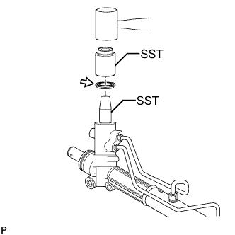
SST J46221
Lubricate the new spool shaft seal with grease.
Install the spool shaft seal onto the spool shaft of the valve assembly.
Using the larger end of the SST and a rubber mallet, gently tap the spool shaft seal into the housing assembly.
SST J46193
Remove the SST from the housing assembly and the valve spool shaft.
Install the new nut onto the pinion and valve assembly while holding the spool shaft with the SST.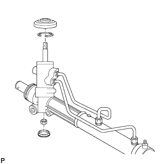
- SST
- 09616-00011
- Torque:
- 30 N*m{ 306 kgf*cm , 22 ft.*lbf }
- NOTICE:
- The spool shaft must be held in place during the following step.
Install the new dust cover on to the housing assembly.
Install the new retaining ring into the groove in the top of the valve assembly of the housing assembly.
Install the new spool shaft boot.
| 7. INSTALL RACK BEARING ASSEMBLY |
Lubricate the rack bearing assembly and o-ring with lithium base grease.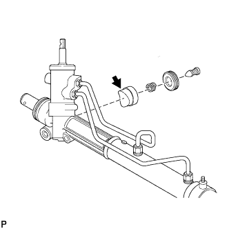
Clean the inside of the rack and pinion housing assembly before installing the adjuster plug.
Install the rack bearing assembly with o-ring, adjuster spring and adjuster plug.
Turn the new adjuster plug clockwise until it bottoms in the housing assembly.
- Torque:
- 10 N*m{ 102 kgf*cm , 7 ft.*lbf } then turn back 35 to 55 degrees.
Install the sealing plug.
| 8. INSTALL STEERING RACK END SUB-ASSEMBLY |
Install 2 new claw washers.
- HINT:
- Align the claws of the claw washer with the steering rack grooves.
Using SST, install the steering rack end sub-assembly (LH side).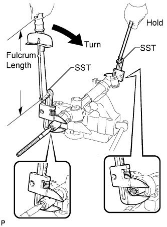
- SST
- 09922-10010
- Torque:
- Without SST:
- 84 N*m{ 851 kgf*cm , 62 ft.*lbf }
- With SST:
- 59 N*m{ 597 kgf*cm , 43 ft.*lbf }
- NOTICE:
- Use SST 09922-10010 as shown in the illustration.
- Use a torque wrench with a fulcrum length of 345 mm (13.58 in.).
- This torque value is effective when SST is parallel to the torque wrench.
- Use SST 09922-10010 as shown in the illustration.
- HINT:
- Using SST, hold the steering rack and install the steering rack end sub-assembly (LH side).
Using SST, install the steering rack end sub-assembly (RH side).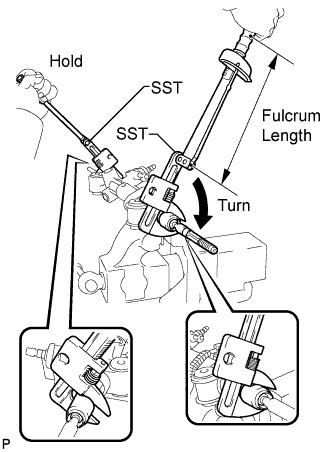
- SST
- 09922-10010
- Torque:
- Without SST:
- 84 N*m{ 851 kgf*cm , 62 ft.*lbf }
- With SST:
- 59 N*m{ 597 kgf*cm , 43 ft.*lbf }
- NOTICE:
- Use SST 09922-10010 as shown in the illustration.
- Use a torque wrench with a fulcrum length of 345 mm (13.58 in.).
- This torque value is effective when SST is parallel to the torque wrench.
- Use SST 09922-10010 as shown in the illustration.
- HINT:
- Using SST, hold the steering rack end sub-assembly (LH side) and install the steering rack end sub-assembly (RH side).
Using a brass bar and a hammer, stake the RH and LH claw washers.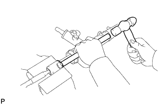
- NOTICE:
- Avoid any impact to the steering rack.
Ensure that the holes of the RH and LH rack ends are not clogged with grease.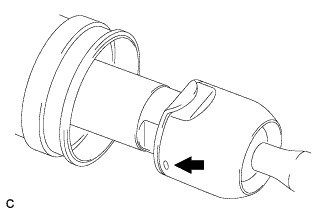
- HINT:
- If the holes are clogged, the pressure inside the boot will change after it is assembled and the steering wheel is turned.
| 9. INSTALL NO. 2 STEERING RACK BOOT |
Apply silicone grease to the inside of the small opening of the No. 2 steering rack boot.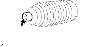
Install the No. 2 steering rack boot to the groove on the rack housing.
- NOTICE:
- Be careful not to damage or twist the No. 2 steering rack boot.
| 10. INSTALL NO. 1 STEERING RACK BOOT |
- HINT:
- Perform the same procedure as for the No. 2 steering rack boot.
| 11. INSTALL NO. 2 STEERING RACK BOOT CLAMP |
Using SST, tighten the RH and LH No. 2 steering rack boot clamps as shown in the illustration.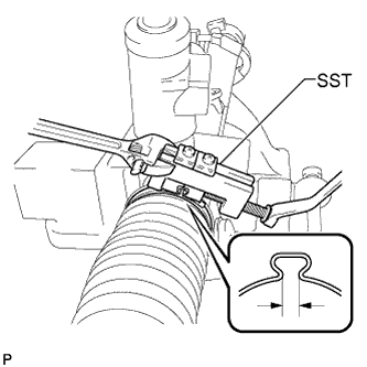
- SST
- 09521-24010
- Clearance:
- 2 mm (0.079 in.) or less
- NOTICE:
- Be careful not to damage the steering rack boots.
| 12. INSTALL STEERING RACK BOOT CLIP |
Using pliers, install the RH and LH steering rack boot clips.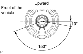
- NOTICE:
- Make sure that each clip claw is positioned within the area shown in the illustration.
Using SST, turn the pinion and check that the rack boots expand and contract smoothly.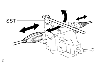
- SST
- 09616-00011