Headlight Beam Level Warning Circuit
Circuit diagnosis · Vehicles built Oct 2006 – May 2009
DESCRIPTION
The headlight beam level control system warning light in the combination meter assembly comes on for approximately 3 seconds when the ignition switch is turned on (IG). The warning light also comes on when the headlight leveling ECU detects a malfunction.WIRING DIAGRAM
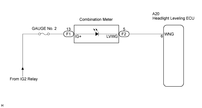

INSPECTION PROCEDURE
| 1. INSPECT COMBINATION METER ASSEMBLY |

Remove the combination meter assembly.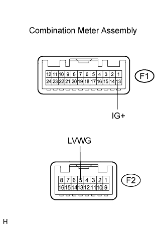
Apply battery voltage to the combination meter assembly connector.
Check that the warning light comes on.
- OK:
Measurement Condition
Specified Condition
Battery positive (+) → Terminal F1-13 (IG+)
Battery negative (-) → Terminal F2-5 (LVWG)
Warning light comes on.
|
|
||||

| OK | |
 |
| 2. CHECK HARNESS AND CONNECTOR (BATTERY - COMBINATION METER ASSEMBLY) |
Disconnect the F1 combination meter assembly connector.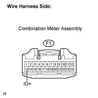
Measure the voltage according to the value(s) in the table below.
- Standard voltage:
Tester Connection
Switch Condition
Specified Condition
F1-13 (IG+) - Body ground
Ignition switch on (IG)
10 to 14 V
Ignition switch off
Below 1 V
|
|
||||
| OK | |
|
| 3. CHECK HARNESS AND CONNECTOR (COMBINATION METER ASSEMBLY - ECU) |
Disconnect the F2 combination meter assembly connector.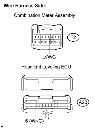
Disconnect the A20 headlight leveling ECU connector.
Measure the resistance according to the value(s) in the table below.
- Standard resistance:
Tester Connection
Condition
Specified Condition
A20-6 (WNG) - F2-5 (LVWG)
Always
Below 1 Ω
A20-6 (WNG) - Body ground
Always
10 kΩ or higher
|
|
||||
| OK | ||
 |
||
| ||