2006-2011 Camry Aurion · Service Manual BODY ELECTRICAL

Reverse Signal Circuit

Circuit diagnosis · Vehicles built Oct 2006 – May 2009

Versions by build date: Jun 2006 – Sep 2006 Oct 2006 – May 2009 from Jun 2009

DESCRIPTION

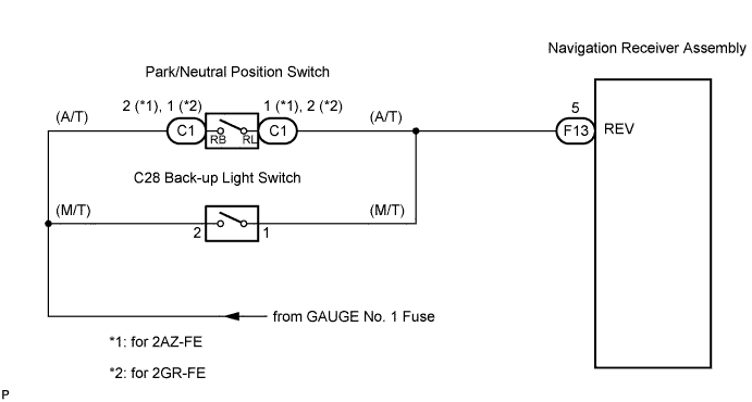
The navigation receiver assembly receives a reverse signal from the park/neutral position switch and information about the GPS antenna, and then adjusts vehicle position.

WIRING DIAGRAM

E137751E03

INSPECTION PROCEDURE


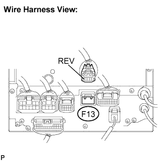
1. INSPECT NAVIGATION RECEIVER ASSEMBLY

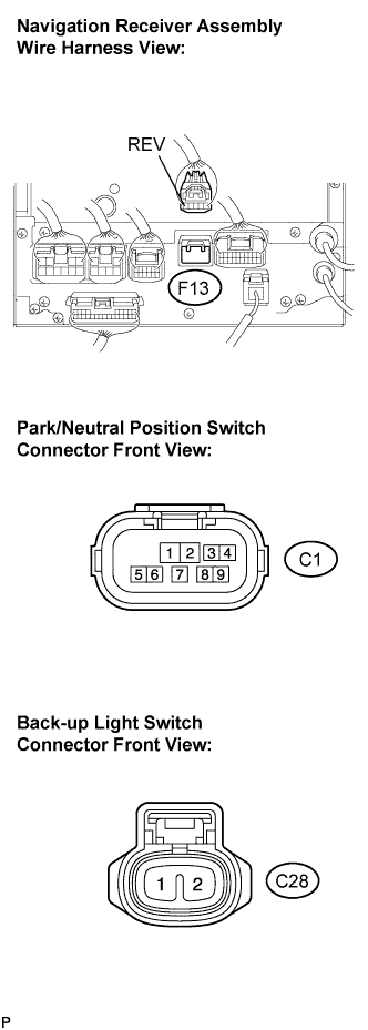
  1. E137752E01
    Disconnect the navigation receiver assembly connector F13.

  1. Measure the voltage according to the value(s) in the table below.
    Standard voltage:
    Tester connection
    Condition
    Specified condition
    F13-5 (REV) - Body ground
    Ignition switch on (IG).
    Shift lever is moved to R position.
    10 to 14 V
    F13-5 (REV) - Body ground
    Ignition switch on (IG).
    Shift lever is moved to any position except R.
    Below 1 V


OK
REPLACE NAVIGATION RECEIVER ASSEMBLY
NG


2. CHECK HARNESS AND CONNECTOR

  1. E137753E01
    Disconnect the navigation receiver assembly connector F13 and park/neutral position switch connector C1 or back-up light switch connector C28.

  1. Measure the resistance according to the value(s) in the table below.

    Standard resistance:
    Tester connection
    Condition
    Specified condition
    F13-5 (REV) - C1-1 (*1)
    Always
    Below 1 Ω
    F13-5 (REV) - C1-2 (*2)
    Always
    Below 1 Ω
    F13-5 (REV) - C28-1 (*3)
    Always
    Below 1 Ω
    F13-5 (REV) - Body ground
    Always
    10 kΩ or higher

*1: A/T (for 2AZ-FE)
*2: A/T (for 2GR-FE)
*3: M/T


NG
REPAIR OR REPLACE HARNESS OR CONNECTOR
OK


3. CHECK VEHICLE TYPE
  1. Choose type to be inspected.


Result:
Type
Go to step
A/T
A
M/T
B


B
Go to step 5
A


4. INSPECT PARK/NEUTRAL POSITION SWITCH

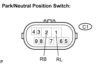
  1. E120122E20
    Disconnect the park/neutral position switch connector C1.

  1. Measure the resistance according to the value(s) in the table below.

    Standard resistance:
    Tester connection
    Condition
    Specified condition
    C1-1 (RL) - C1-2 (RB)
    Shift lever is moved to R.
    Below 1 Ω
    C1-1 (RL) - C1-2 (RB)
    Shift lever is moved to any position except R.
    10 kΩ or higher


NG
REPLACE PARK/NEUTRAL POSITION SWITCH
OK

REPAIR OR REPLACE HARNESS OR CONNECTOR

5. INSPECT BACK-UP LIGHT SWITCH

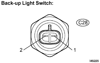
  1. I045225E04
    Disconnect the back-up light switch connector C28.

  1. Measure the resistance according to the value(s) in the table below.
    Standard resistance:
    Tester connection
    Condition
    Specified condition
    C28-1 - C28-2
    Shift lever is moved to R.
    Below 1 Ω
    C28-1 - C28-2
    Shift lever is moved to any position except R.
    10 kΩ or higher


NG
REPLACE BACK-UP LIGHT SWITCH
OK

REPAIR OR REPLACE HARNESS OR CONNECTOR


← Reverse Signal Circuit (Jun 2006 – Sep 2006)Reverse Signal Circuit (from Jun 2009) →