INSPECTION
Inspection · Vehicles built from Jun 2009
| INSPECT PAD LINING THICKNESS |

Using a ruler, measure the pad lining thickness.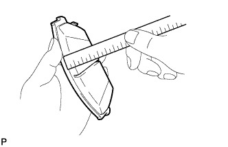

- Standard thickness:
- 12.0 mm (0.472 in.)
- Minimum thickness:
- 2.0 mm (0.0787 in.)
- HINT:
- When replacing the front brake pads with new ones, make sure to replace the brake pad support plate at the same time.
- Be sure to check wear of the front disc after replacing the brake pad with a new one.
- When replacing the front brake pads with new ones, make sure to replace the brake pad support plate at the same time.
| INSPECT BRAKE CYLINDER AND PISTON |
Inspect the cylinder bore and piston for rust or scoring. If necessary, replace the front disc brake cylinder assembly and front disc brake piston.
| INSPECT FRONT DISC BRAKE PAD SUPPORT PLATE |
Inspect the brake pad support plates. If necessary, replace the brake pad support plate.
- HINT:
- When replacing the front brake pads with new ones, make sure to replace the brake pad support plate at the same time.
- Make sure that the pad support plate has sufficient rebound, has no deformation, cracks or wear, and that all rust and dirt are cleaned off.
- When replacing the front brake pads with new ones, make sure to replace the brake pad support plate at the same time.
| INSPECT DISC THICKNESS |
Install the front disc. (Click here)
Using a micrometer, measure the disc thickness.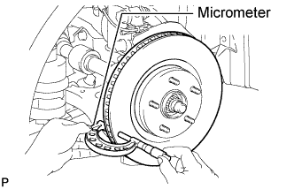
- Standard thickness:
- 28.0 mm (1.102 in.)
- Minimum thickness:
- 25.0 mm ( 0.983 in.)
| INSPECT DISC RUNOUT |
Using SST to hold the front disc, tighten the disc with the 3 hub nuts.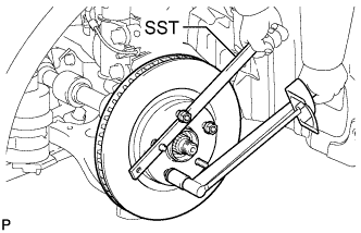
- SST
- 09330-00021
- HINT:
- Use the SST to hold the disc while torquing the nuts.
- Torque:
- 103 N*m{ 1,050 kgf*cm , 76 ft.*lbf }
Using a dial indicator, measure the disc runout 10 mm (0.39 in.) away from the outer edge of the disc.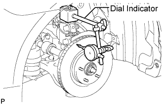
- Maximum disc runout:
- 0.05 mm (0.0020 in.)
- NOTICE:
- Keep the magnet of the dial indicator away from the axle hub and speed sensor.
- Install the dial indicator to the shock absorber.
- Keep the magnet of the dial indicator away from the axle hub and speed sensor.
If the runout exceeds the maximum value, change the installation positions of the disc and axle so that the runout will become minimal. If the runout exceeds the maximum even after the installation positions are changed, check the bearing play in the axial direction and the axle hub runout (Click here). If the bearing play and the axle hub runout are normal and if the disc thickness is not within the specified range, grind the disc. If the disc thickness is less than the minimum, replace the disc.
Remove the 3 hub nuts.
Remove the front disc.