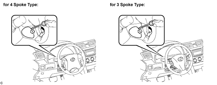
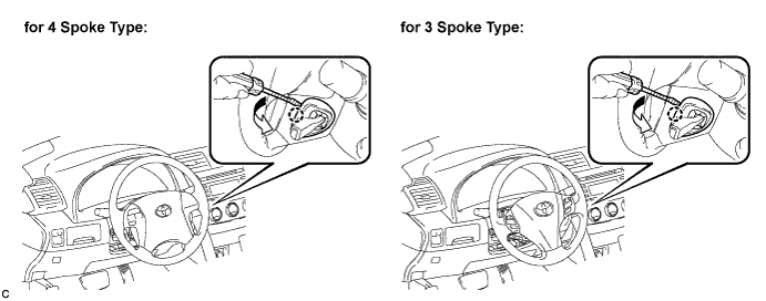
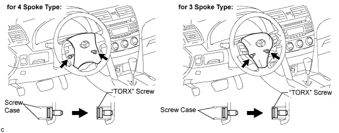
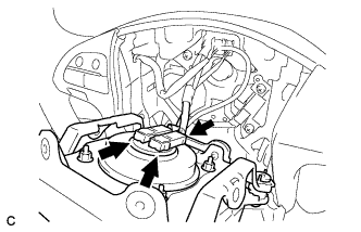
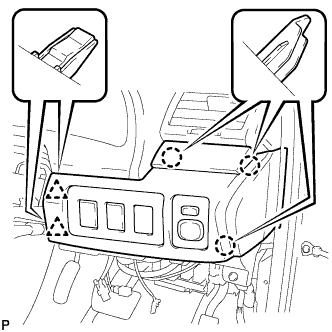
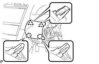
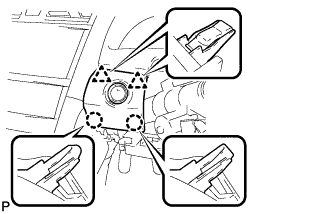
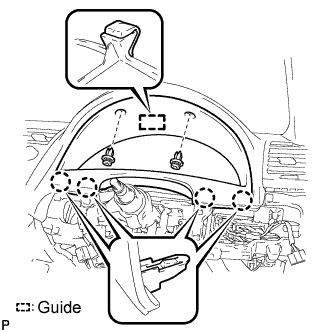
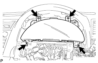
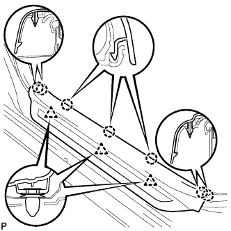
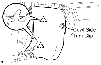
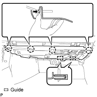
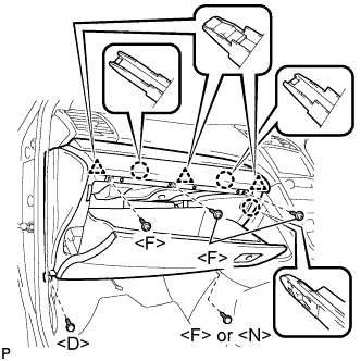
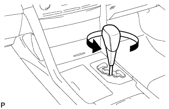
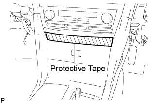
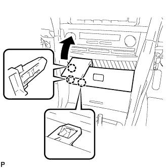
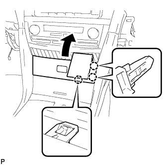
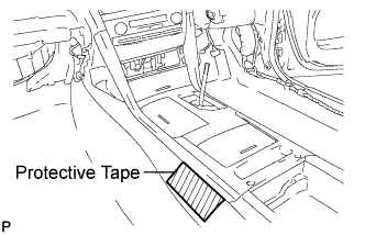
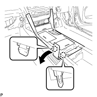
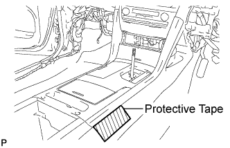
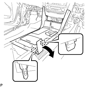
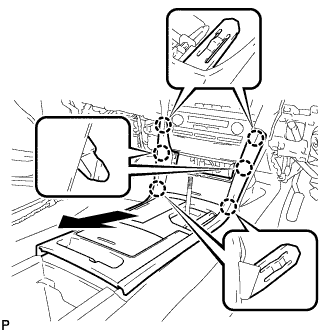
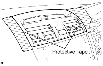
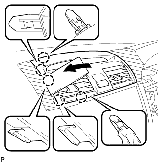
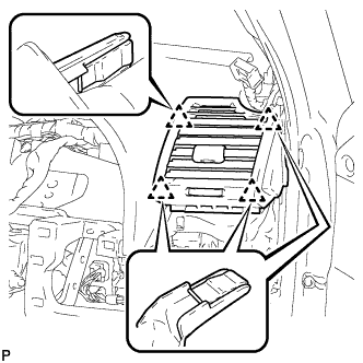
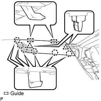
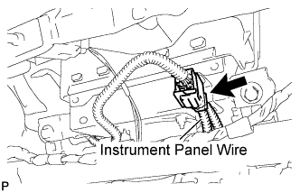
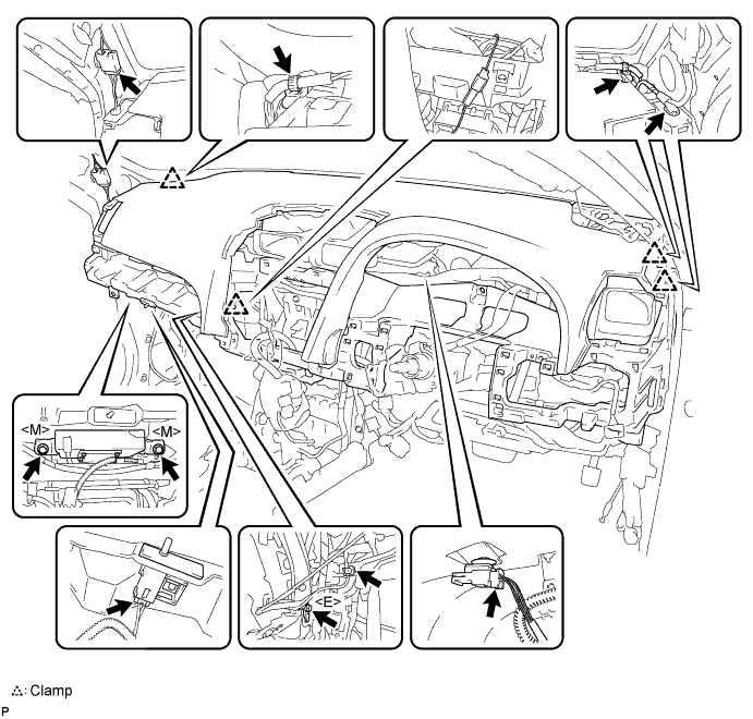
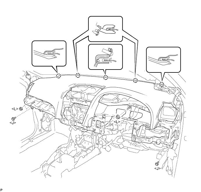
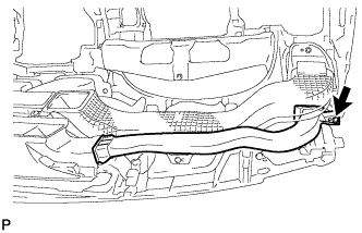
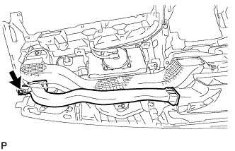
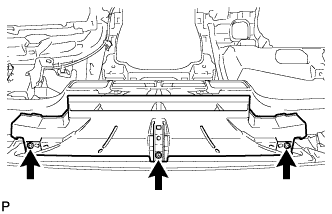
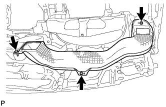
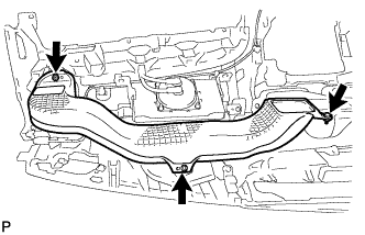
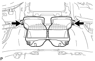
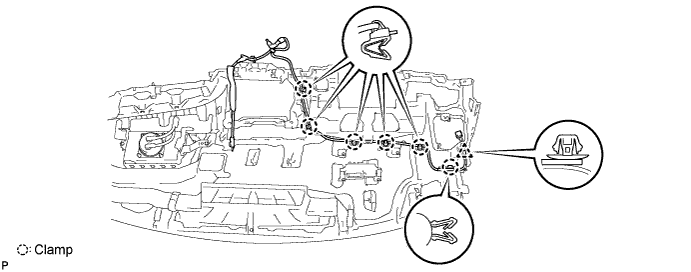
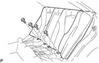
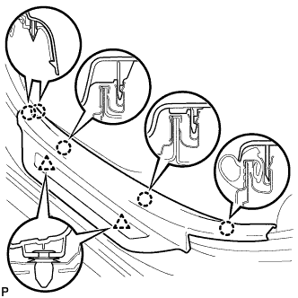
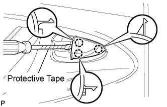
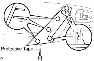
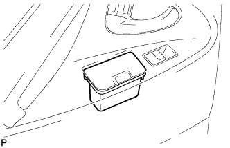
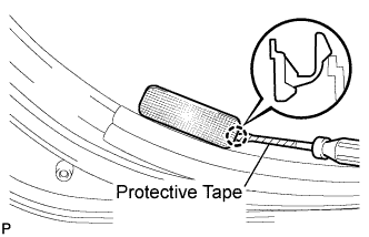
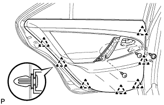
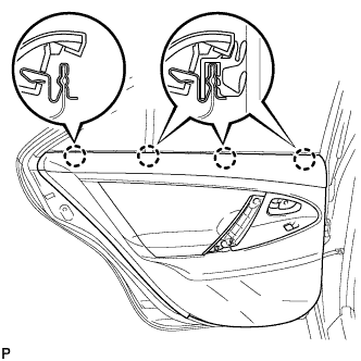
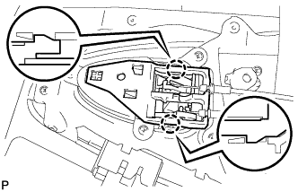
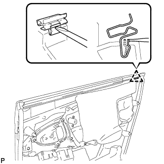
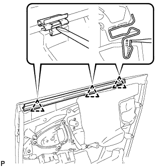
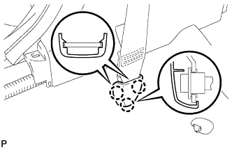
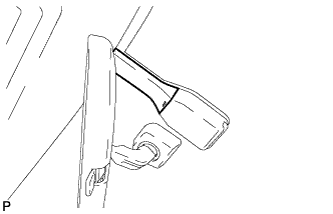
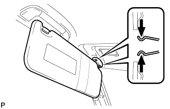
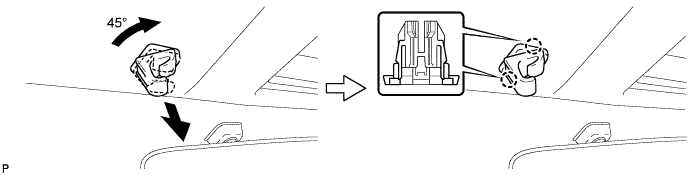
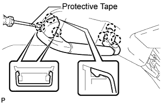
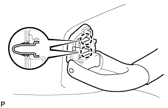
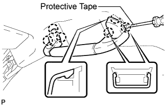
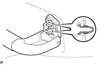
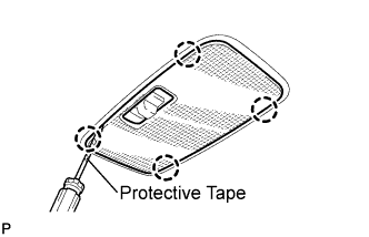
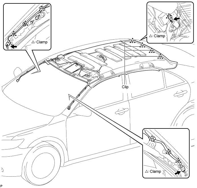
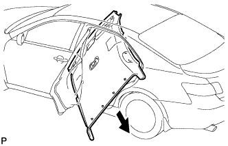
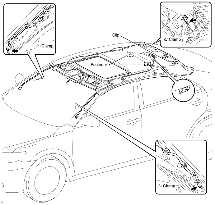
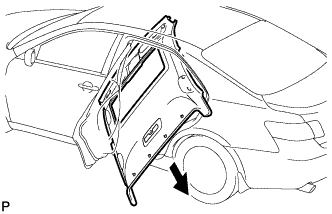
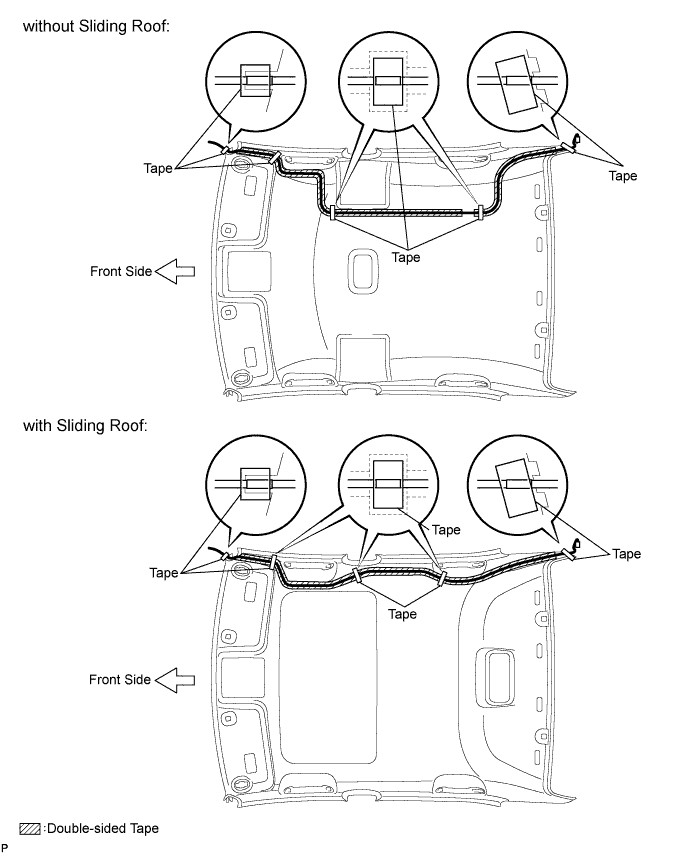
Apply protective tape to the areas shown in the illustration.
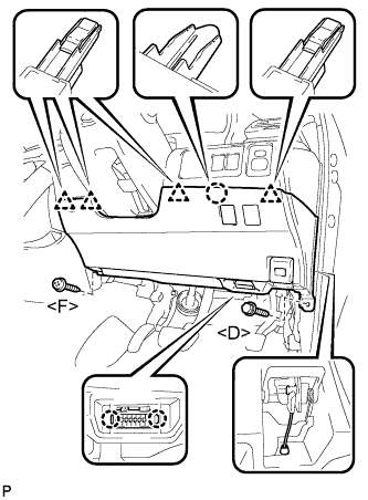
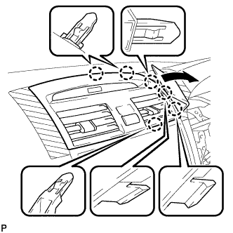
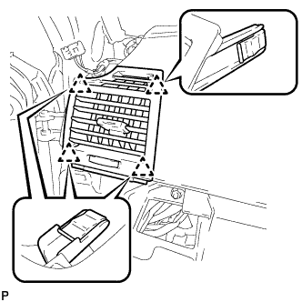
Using a moulding remover, disengage the 6 claws as shown in the illustration.
Using a moulding remover, disengage the 5 claws as shown in the illustration.
Disconnect each connector and remove the instrument panel No. 2 register assembly.
26.
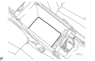
REMOVE CONSOLE BOX CARPET
Remove the console box carpet.
27.
REMOVE CONSOLE BOX ASSEMBLY
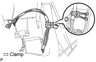
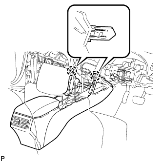
Disengage the clamp.
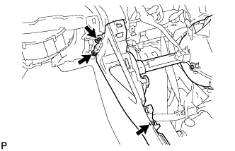
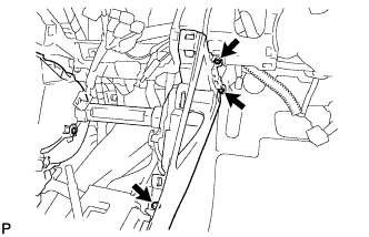
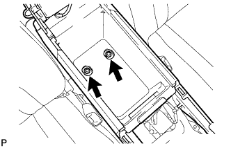
Remove the 3 screws <H>.
Remove the 3 screws <H>.
Remove the 2 bolts <I>.
Disengage the 2 claws and remove the console box assembly.
28.
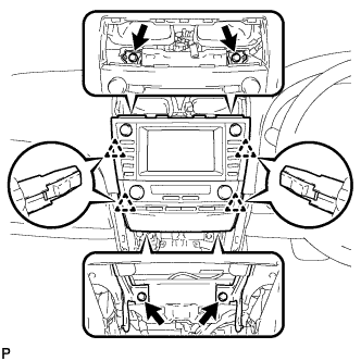
REMOVE RADIO RECEIVER WITH HEATER CONTROL PANEL ASSEMBLY (w/ Radio Receiver)
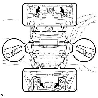
Remove the 4 bolts.
Pull the radio receiver with heater control panel assembly toward the rear of the vehicle and disengage the 4 clips.
Disconnect each connector and remove the radio receiver with heater control panel assembly.
29.
REMOVE NAVIGATION RECEIVER WITH HEATER CONTROL PANEL ASSEMBLY (w/ Navigation System)
Remove the 4 bolts.
Pull the navigation receiver with heater control panel assembly toward the rear of the vehicle and disengage the 4 clips.
Disconnect each connector and remove the navigation receiver with heater control panel assembly.
30.
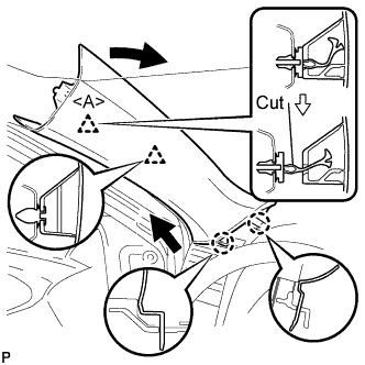
REMOVE FRONT PILLAR GARNISH LH
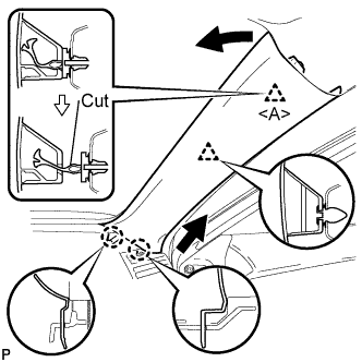
Pull the upper part of the garnish toward the inside of the cabin and disengage the 2 clips.
Cut off the clip <A>.
Disengage the 2 claws and remove the front pillar garnish LH.
Remove the clip <A> from the vehicle body.
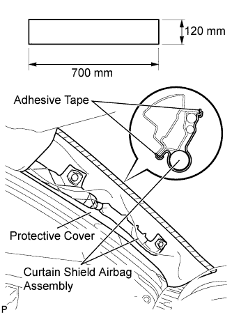
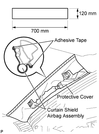
Protect the curtain shield airbag assembly.
Cover the airbag with a 700 mm (27.56 in.) x 120 mm (4.72 in.) cloth or piece of nylon and fix the ends of the cover with tape, as shown in the illustration.
NOTICE:
Cover the curtain shield airbag with a protective cover as soon as the front pillar garnish is removed.
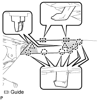
Disengage the 2 guides and remove the instrument panel No. 1 speaker panel sub-assembly.
33.
REMOVE FRONT NO. 2 SPEAKER ASSEMBLY (for LH Side)
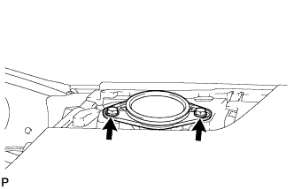
Remove the 2 bolts and front No. 2 speaker assembly.
Disconnect the connector.
34.
REMOVE FRONT PILLAR GARNISH RH
Pull the upper part of the garnish toward the inside of the cabin and disengage the 2 clips.
Cut off the clip <A>.
Disengage the 2 claws and remove the front pillar garnish RH.
Remove the clip <A> from the vehicle body.
Protect the curtain shield airbag assembly.
Cover the airbag with a 700 mm (27.56 in.) x 120 mm (4.72 in.) cloth or piece of nylon and fix the ends of the cover with tape, as shown in the illustration.
NOTICE:
Cover the curtain shield airbag with a protective cover as soon as the front pillar garnish is removed.
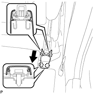
Using a screwdriver, disengage the 4 claws and remove the front seat rear inner track bracket cover.
HINT:
Tape the screwdriver tip before use.
50.
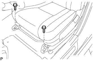
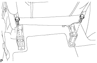
REMOVE FRONT SEAT ASSEMBLY RH (for Power Seat)
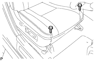
Operate the power seat switch knob and move the seat to the rearmost position.
Remove the 2 bolts on the front seat track bracket.
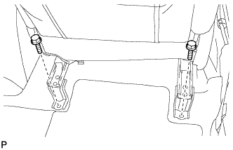
Operate the power seat switch knob and move the seat to the position farthest forward.
Remove the 2 bolts on the rear seat track bracket.
Disconnect the cable from the negative (-) battery terminal.
CAUTION:
Wait at least 90 seconds after disconnecting the cable from the negative (-) battery terminal to prevent the airbag and seat belt pretensioner from deploying (Click here).
Disconnect the connectors under the seat. Then remove the front seat assembly.
51.
REMOVE FRONT SEAT HEADREST ASSEMBLY (for Power Seat)
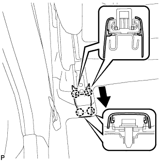
Using a screwdriver, disengage the 4 claws and remove the inner seat track bracket cover.
HINT:
Tape the screwdriver tip before use.
58.
REMOVE FRONT SEAT ASSEMBLY LH (for Manual Seat)
Move the front seat assembly to the rearmost position by operating the slide handle.
Remove the 2 bolts on the front seat track bracket.
Move the front seat assembly fully forward by operating the slide handle.
Remove the 2 bolts on the rear seat track bracket.
Move the front seat assembly to the center position and adjust the seatback to the vertical position by operating the slide and reclining adjuster release handle.
Using a screwdriver, disengage the 4 claws and remove the lens cover.
HINT:
Tape the screwdriver tip before use.
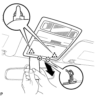
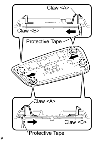
Using a screwdriver, disengage the 2 claws <A> as shown in the illustration.
HINT:
Tape the screwdriver tip before use.
Disengage the 2 claws <B> and remove the No. 1 room light assembly.
Disconnect the room light connector.
94.
REMOVE SPOT LIGHT ASSEMBLY (w/ Sliding Roof)
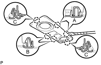
Using a screwdriver, disengage the 2 claws labeled A and 2 claws labeled B from the vehicle body.
HINT:
Tape the screwdriver tip before use.
Using a screwdriver, disengage the 2 claws labeled C and remove the spot light assembly from the headlining.
HINT:
Tape the screwdriver tip before use.
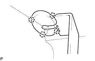
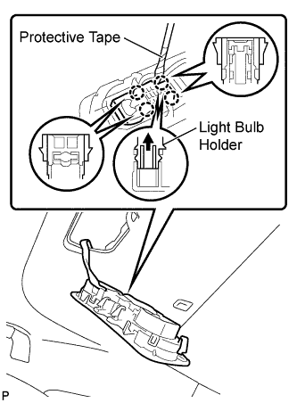
Using a screwdriver, disengage the 4 claws.
HINT:
Tape the screwdriver tip before use.
Pull the light bulb holder in the direction indicated by the arrow in the illustration to detach the claw. Then remove the spot light assembly from the light bulb holder.
95.
REMOVE SUN ROOF OPENING TRIM MOULDING (w/ Sliding Roof)