Clock Display Circuit
Circuit diagnosis · Vehicles built from Jun 2009
Versions by build date: Jun 2006 – Sep 2006 Oct 2006 – May 2009 from Jun 2009
DESCRIPTION
In this circuit, the clock assembly receives auto dimmer signals from the main body ECU using the direct line. When the clock assembly receives an auto dimmer signal, it dims the clock illumination. The main body ECU determines whether it is daytime, twilight, or nighttime based on the waveform transmitted from the automatic light control sensor. If the main body ECU determines that it is daytime, the ECU does not send auto dimmer signals. Therefore, the clock illumination (warning and indicator lights) will not dim even if the driver accidentally turns the light control switch to the TAIL or HEAD position in daytime.- HINT:
- If there is a malfunction in automatic light control sensor, DTC B1244 is output (Click here for 2AZ-FE, Click here for 2GR-FE).
WIRING DIAGRAM
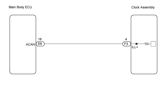

INSPECTION PROCEDURE
| 1. CHECK HARNESS AND CONNECTOR (CLOCK ASSEMBLY - MAIN BODY ECU) |

Disconnect the E6 and F3 connectors.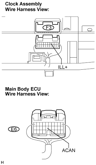
Measure the resistance according to the value(s) in the table below.
- Standard resistance:
Tester Connection
Condition
Specified Condition
E6-16 (ACAN) - F3-4 (ILL+)
Always
Below 1 Ω
F3-4 (ILL+) - Body ground
Always
10 kΩ or higher
|
|
||||

| OK | |
 |
| 2. INSPECT MAIN BODY ECU |
Reconnect the E6 connector.
Measure the voltage according to the value(s) in the table below.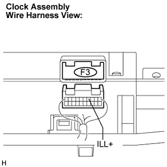
- Standard voltage:
Tester Connection
Condition
Specified Condition
F3-4 (ILL+) - Body ground
Ignition switch on (IG), cover the automatic light control sensor by hand, and light control switch TAIL/HEAD
10 to 14 V
|
|
||||
| OK | ||
 |
||
| ||