Status Indicator LEDs Do Not Illuminate
Circuit diagnosis · Vehicles built from Oct 2006
DESCRIPTION
The red and green status indicator LEDs in the roof console box indicate the current status of the Toyota Link system.The mayday ECU activates the LEDs by switching a 12 V power supply to each LED ON or OFF.
The brightness of the LEDs is controlled by the roof console box electronics, which will vary the brightness of the LEDs depending on the ambient light and the engine switch condition.
If the ambient light is low the brightness of the LEDs will be decreased when the engine switch is on (IG). If the ambient light is high there will be no change to the brightness of the LEDs when the engine switch is turned on (IG).
The colour of the LED indicates the status of the system. If there is a system fault during a call, the LED will flash red; if there are no system faults, then the LED will flash green.
INSPECTION PROCEDURE
| 1. SELECT ACTIVE MODE |

Select: System Menu / Mode.
Does the TDT display the Operating mode, "Active"?
|
|
||||

| YES | |
 |
| 2. PERFORM ACTIVE TEST |
Select: System Menu / Diagnosis / Active Test.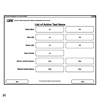

Using the TDT, select Red LED: ON and OFF.
Observe the LED.
Does the red LED turn ON and OFF?
- HINT:
- Red LED OK
|
|
||||

| NO | |
|
| 3. CHECK ROOF CONSOLE BOX VOLTAGE |
Connect a digital multimeter between roof console box connector Q16 terminal 5 and ground.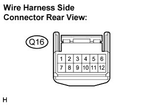
Turn the red LED ON and OFF as in the previous step and check for voltage.
- OK:
- 12 - 14 V
|
|
||||
| NG | |
|
| 4. CHECK THE MAYDAY ECU VOLTAGE |
Connect a digital multimeter between mayday ECU unit connector N46 terminal 19 and ground.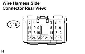
Turn the red LED ON and OFF as in the previous step.
Measure the voltage.
- OK:
- 12 - 14 V
|
|
||||
| OK | ||
 |
||
| ||
| 5. PERFORM ACTIVE TEST |
Select: System Menu / Diagnosis / Active Test.
Using the TDT, select Green LED: ON and OFF.
Observe the LED.
Does the green LED turn ON and OFF?
- HINT:
- Green LED OK
|
|
||||
| NO | |
|
| 6. CHECK ROOF CONSOLE BOX VOLTAGE |
Connect a digital multimeter between roof console box connector Q16 terminal 11 and ground.
Turn the green LED ON and OFF as in the previous step and check for voltage.
- OK:
- 12 - 14 V
|
|
||||
| NG | |
|
| 7. CHECK THE MAYDAY ECU VOLTAGE |
Connect a digital multimeter between mayday ECU unit connector N46 terminal 14 and ground.
Turn the green LED ON and OFF as in the previous step and check for voltage.
- OK:
- 12 - 14 V
|
|
||||
| OK | ||
|
||
| ||
| 8. CHECK ROOF CONSOLE BOX GROUND |
Disconnect the roof console box connector Q16.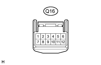
Connect a digital multimeter between terminal 8 and ground and check for continuity.
- OK:
- Less than 1 Ω
|
|
||||
| NG | ||
|
||
| ||
| 9. CHECK MAYDAY ECU WIRE HARNESS |
Disconnect the mayday ECU connectors A and B.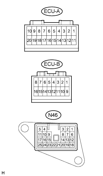
Check for continuity between the mayday ECU unit connector N46 and connectors A and B.
- OK:
- Less than 1 Ω
|
|
||||
| OK | |
|
| 10. CHECK MAYDAY ECU CONNECTORS |
Are the mayday ECU connectors tight?
|
|
||||
| YES | ||
|
||
| ||