DIAGNOSIS SYSTEM
Troubleshooting · Vehicles built from Jun 2009
Versions by build date: Oct 2006 – May 2009 from Jun 2009
| CONNECTING THE TOYOTA LINK DIAGNOSTIC TOOL |
The diagnostic connector is located on the mayday ECU unit, under the parcel tray in the rear compartment, refer to Parts Location (Click here).
| INTRODUCTION |
PC REQUIREMENTS
The following PC requirements are recommended for the operation of the Toyota Link Diagnostic Tool.- Computer: Pentium 4, 2.8 GHz
- RAM: 256 Mb.
- Operating System: Windows XP
- CD ROM: CD Reader
- Serial Port: 9 Pin RS-232 Serial Port
- Computer: Pentium 4, 2.8 GHz
PC NAVIGATION
The following methods may be used to navigate through the TDT.Mouse
- Use the mouse to point and click on the required buttons.
- Use the mouse to point and click on the required buttons.
Keyboard Hot Key Navigation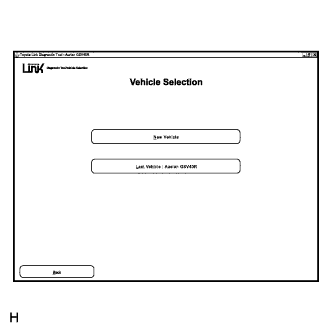

- You can navigate using the hot keys, to use these keys press the ALT key plus the letter that is underlined. In the illustration opposite to use the hot key, you would press ALT + N.
- Use the TAB and ARROW keys to scroll through the information lists.
- The TAB and ENTER keys may also be used to highlight and select the required buttons.
- HINT:
- For audio volume adjustment, snapshot trigger set-up and com port set up, when the TAB key is used to navigate from button to button, the colour of the drop down button does not change. Ensure that the number of times the TAB button is pressed is counted; then use the ENTER key to open the required drop-down menu.
- You can navigate using the hot keys, to use these keys press the ALT key plus the letter that is underlined. In the illustration opposite to use the hot key, you would press ALT + N.
STAND-BY MODE
The Mayday ECU will adopt the stand-by mode, 2 minutes after the engine switch is turned off and a door is opened and closed or 30 minutes after the engine switch is turned off.
Once the stand-by mode is adopted, the TDT will not be able to communicate with the mayday ECU.
If communication with the mayday ECU is lost whilst the TDT is being used, open a door and cycle the engine switch on (IG) to force the mayday ECU to exit from the stand-by mode.EXPORT TO CSV
For the Data List and Snapshot items, an Export to CSV button is provided at the bottom of the screen. This allows the data to be exported to c:/TDT Exports as a comma separated values (CSV) file.
This file may be emailed as a CSV file or imported into Microsoft Excel for analysis.
| TDT SYSTEM FUNCTIONS |
TDT UNLOCKING KEY
With the TDT loaded onto your PC / Laptop, start the program by double clicking on the icon on your Desktop.
Phone Toyota Services on the 1800 number provided on the TDT Screen to generate the Unlocking Code for your TDT.
Once you have your Unlocking Code, you now have access to the Toyota Link Diagnostic Tool.
TOYOTA LINK DIAGNOSTIC TOOL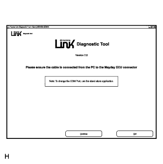
Ensure the diagnostic cable is connected correctly from your PC to the mayday ECU diagnostic connector located in the luggage compartment.
While in the opening screen, select: Continue.
VEHICLE SELECTION
Select the Vehicle required:- New Vehicle, or
- Continue with the last Vehicle diagnosed with the TDT.
- New Vehicle, or
CONFIRM VIN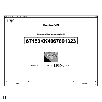
The TDT will confirm the VIN read directly from the mayday ECU.Select:
- Back to return to the Vehicle Selection menu, or
- Continue.
- HINT:
- If the VIN read is not the same as the actual vehicle VIN, the VIN may be updated for the TDT records.
- Updating the records here only changes the VIN registered for saved snapshots, it does not update the VIN stored in the mayday ECU.
- If the incorrect VIN is stored, the mayday ECU will need to be replaced (Click here).
- Back to return to the Vehicle Selection menu, or
SYSTEM MENU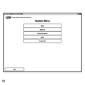
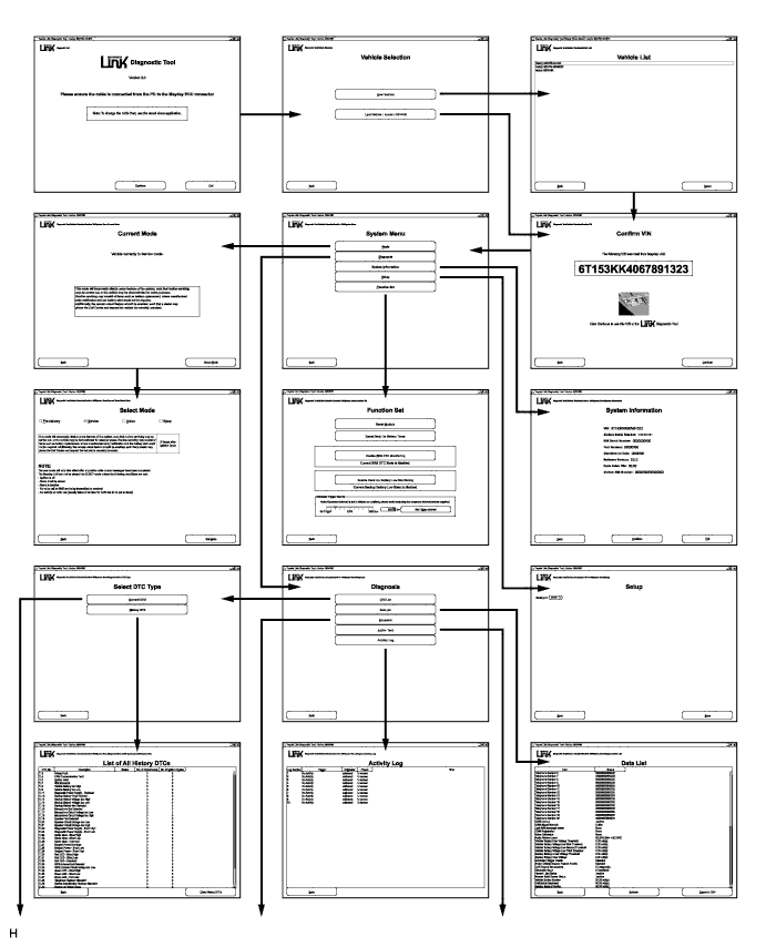
The TDT has five system functions for diagnosing the mayday ECU. The five systems functions are:Mode:
Displays the vehicle's current operating mode, and can re-program the mayday ECU operating mode.Diagnosis:
Displays the status of inputs and outputs of the mayday ECU, including DTCs, Data List, Snapshot, Active Tests and Telephone Activity Log.System Information:
Displays the mayday ECU System Information.Setup:
Displays the Serial Com. Port in use.Function Set:
Performs system functions, such as Module Reset, Backup Battery Timer Reset, Enable SRS Monitoring, Backup Battery Low Monitoring and Audio Volume Setting.
MODE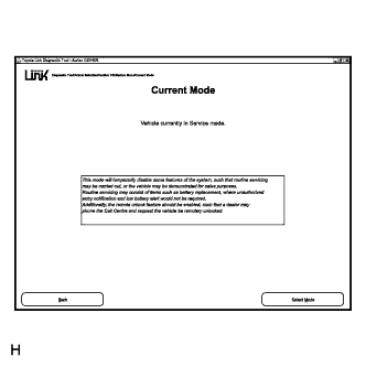
The operating mode can be re-programmed in this screen.Select: Mode
Press: Select Mode, to re-program the operating mode.
Click on the desired operating mode; then click: Set Mode. This will re-program the operating mode.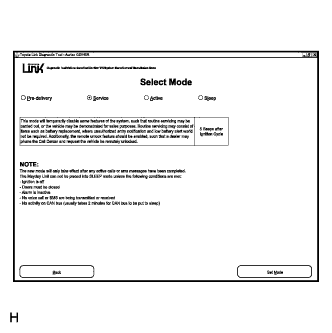
The TDT will then return to the Current Mode screen and verify that the operating mode has been changed.Select: Back to return to the System menu.
TDT ERROR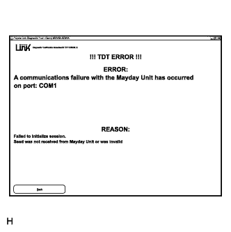
The TDT has the ability to recognize an anomaly in the system when attempting to diagnose the mayday ECU. When this occurs, the TDT will highlight the TDT ERROR screen with the description for the current error.
To return to the System menu, select: Back.DIAGNOSIS
The TDT Diagnosis menu has five diagnostic functions for diagnosing the Toyota Link system. The five diagnosis functions are:DTC List:
The TDT displays and clears current and history DTCs.Data List:
The TDT displays the status of inputs and outputs of the mayday ECU.Snapshot:
The TDT captures mayday ECU data before and after a forced manual trigger.Active Test:
The TDT performs system function tests to assist in problem isolation during troubleshooting.Activity Log:
The TDT records all incoming and outgoing message activity, including phone calls and SMS messages.
DTC LIST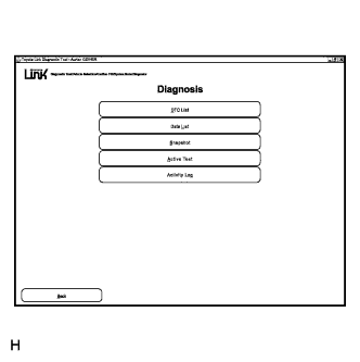
In this diagnosis function, DTCs stored by the mayday ECU can be displayed or cleared.
When Toyota Link Diagnostic Trouble Codes DTC List is selected, the following two modes are available:
Current DTCs: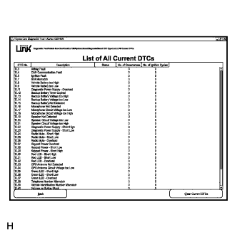
All current DTCs will be displayed as List of All Current DTCs.
When this function is selected, the TDT will display the following information:- The DTC number
- The DTC description
- The DTC status
- The number of occurrences
- The number of ignition cycles since the DTC last reset
- HINT:
- If a DTC is present, DTC Present will be displayed in the status column.
- Even if DTCs have been cleared, the information will still show in the No. of Occurrences and the No. of Ign Cycles columns.
- If a DTC is present, DTC Present will be displayed in the status column.
- The DTC number
History DTCs: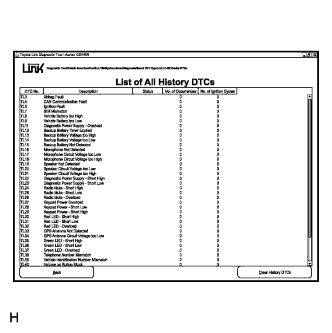
All current DTCs will be displayed as List of all History DTCs.
When this function is selected, the TDT will display the following information:- The DTC number
- The DTC description
- The DTC status
- The number of occurrences
- The number of ignition cycles since the DTC last reset
Even if DTCs have been cleared, the information will still show in the No. of Occurrences and the No. of Ign Cycles columns.- The DTC number
CLEARING THE DTC LIST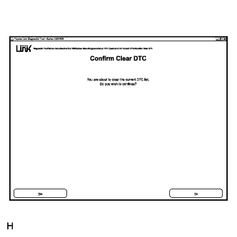
When either Clear Current DTCs or Clear History DTCs is selected, the TDT will display: You are about to clear the DTC list. Do you wish to continue?
If the Yes button is pressed, the TDT will clear all DTC information and automatically return to the List of All Current DTCs or List of All History DTCs, depending on which screen you were first in.
If the No button is pressed, the TDT will exit to the List of All Current DTCs or List of All History DTCs depending on which screen was originally referenced.
DATA LIST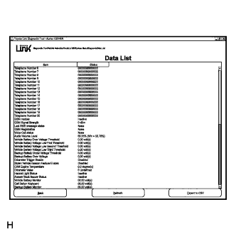
When this diagnosis function is selected, the TDT will check if the Mayday ECU is actually receiving an input or inputs from the various sensor/s, switches or antenna/s.
If the sensor or antenna inputs are not being received, the TDT will then carry out the relevant system diagnosis as defined in diagnostic section in this Service Manual.
The data list information is not real-time information. To update the information, select the refresh button.
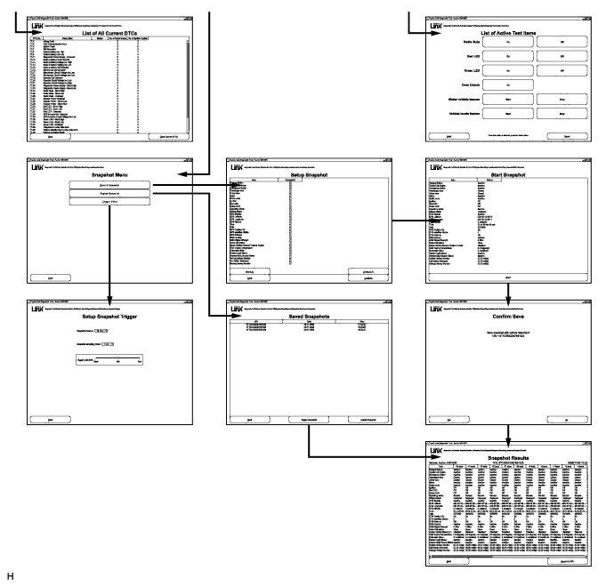
SNAPSHOT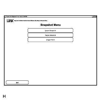
When this diagnosis function is selected, the TDT captures data before and after a forced manual trigger.
The purpose of the snapshot function is to help isolate an intermittent or transient problem by storing mayday ECU data parameters just before and just after a problem occurs.Snapshot Menu:
The TDT can record snapshot data parameters from a selected Trigger Point, enabling a stored memory under the heading Replay Snapshot to be read.
Snapshot Trigger: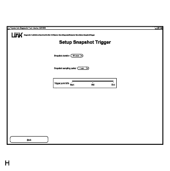
There are three parameters that must be set for the Snapshot Trigger:- Snapshot Duration - The time duration for the snapshot recording can be set between 30 to 60 seconds in 5 second increments.
- Snapshot Sampling Period - The time of each recorded sample within the Snapshot Duration.
- Trigger point - The percentage time period of the snapshot duration prior to or after a selected trigger point.
- Snapshot Duration - The time duration for the snapshot recording can be set between 30 to 60 seconds in 5 second increments.
Record Snapshot: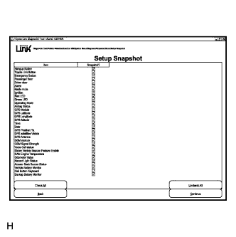
Data list items need to be selected from the Setup Snapshot list, by checking or un-checking the relevant boxes.
Select: Back to return to the Snapshot menu.
Select: Continue to proceed with snapshot recording.
Start Snapshot: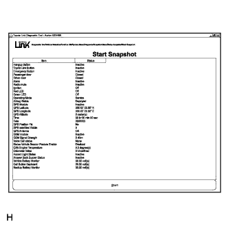
Prior to activating the Start Snapshot button, ensure the checked data list function is displayed on the Start Snapshot screen.
Confirm Save: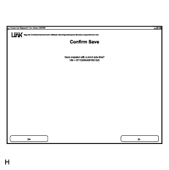
Select: No to return to the Setup Snapshot screen and lose the current snapshot data.
Select: Yes to save the current Snapshot data and VIN.
Snapshot Result: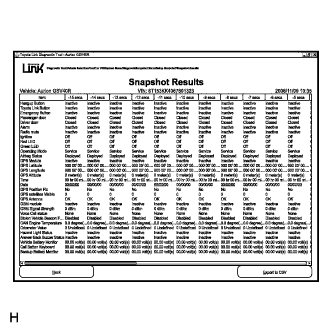
After saving the snapshot data in the Confirm Save screen, the Snapshot Results will be recorded within the snapshot duration selected.
Viewing the entire snapshot is available via the scroll bar at the bottom of the screen.
Select: Export to CSV, to save the data list parameter recording; this file can now be printed or emailed.
Replay Snapshot:
- Select: Replay Snapshot from the Snapshot menu screen.
-
Highlight the saved snapshot, on the saved snapshot screen, that you wish to replay.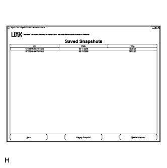
- Click the Replay Snapshot button, this will return you to the snapshots results screen where you can review the selected snapshot recording.
- Select: Replay Snapshot from the Snapshot menu screen.
Delete Snapshot:
- Highlight the saved snapshot recording that you wish to delete.
-
Select: Delete Snapshot button.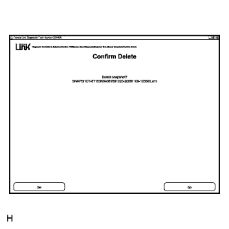
- The Confirm Delete screen appears, requesting confirmation for the saved record to be deleted.
Select either Yes or No.
Yes: Will return you to the saved snapshot screen, where the saved record has been deleted.
No: Will return you to the saved snapshot screen.
- Highlight the saved snapshot recording that you wish to delete.
ACTIVE TEST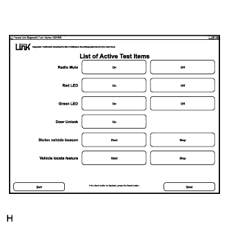
The active tests allow for the testing of various components of the Toyota Link system, such as the status LEDs and radio mute circuit to assist in problem isolation during troubleshooting.
Once the Active tests have been selected, the following List of Active Test Items will be available:- Radio Mute
- Red LED
- Green LED
- Door Unlock
- Stolen vehicle beacon
- Vehicle locate feature
- HINT:
- After Active Tests have been completed, Select: Reset to return to the default settings, then you will be able to select Back to return to the Diagnosis menu.
- Radio Mute
ACTIVITY LOG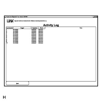
The mayday ECU displays the last ten GSM calls that have been inbound or outbound. This function will also display whether the activity is a phone call or an SMS Message.
Select: Back to return to the Diagnosis menu.
SYSTEM INFORMATION
The mayday ECU will display the system identification information.Select: System Information from the System menu screen.
The following information will be available.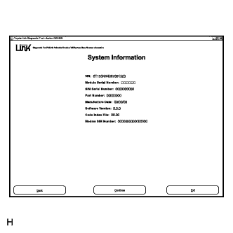
- Vehicle Identification Number (VIN)
- Module Serial Number
- SIM Serial Number
- Part Number
- Manufacture Date
- Software Version
- Code Index File
- Modem SIM Number
- Vehicle Identification Number (VIN)
SET UP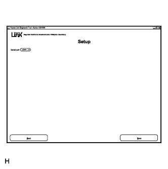
The option of a particular serial port can be selected for the TDT in the Setup function.Serial Port Change Procedure:
- Connect to COM port 1 or use the TDT stand alone function without connection to a vehicle.
- Start the TDT and navigate to the Setup screen.
- Change the Serial port to the desired COM port.
- Shut the TDT down.
- Change the cable from COM port 1 to the chosen COM port.
- HINT:
- If the stand alone version is used, this step is not necessary.
- Restart the TDT.
- Connect to COM port 1 or use the TDT stand alone function without connection to a vehicle.
FUNCTION SET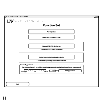
When Function Set has been selected, the following mayday ECU functions will be available:- Reset Module
- Reset Back Up Battery Timer
- Enable SRS DTC Monitoring
- Enable Back Up Battery Low Monitoring
Reset Module:
This function will allow you to reset the mayday ECU. When selected, the TDT will display: The Module is about to be reset. Do you wish to continue?
Selecting the Yes button will reset the Mayday ECU, then return the screen to the Function Set menu, with all the mayday ECU functions reset to their default setting.
Selecting the No button will return the screen to the Function Set menu, with all mayday ECU functions current. On completion of the reset, select: Back to return to the System menu.
Reset Battery Backup Timer: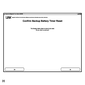
This function allows you to reset the backup battery timer and should only be performed after the backup battery has been replaced. When selected, the TDT will display: The backup battery timer is about to be reset. Do you wish to continue?
Selecting the Yes button will reset the backup battery timer to zero, then return the screen to the Function Set menu, with the backup battery timer function reset to zero seconds.
Selecting the No button will return the screen to the Function Set menu, with the backup battery timer function current.
On completion of the reset, select: Back to return to the System menu.
Enable SRS DTC Monitoring:
The Toyota Link system monitors the SRS accident sensing circuit for any related faults. The DTC fault code TL3 will set if the mayday ECU detects a fault in the SRS sensing circuit.
This will be considered by the mayday ECU as an airbag fault and the SRS system as unhealthy.
As well as setting a DTC, the mayday ECU will emit five quick beeps and send an SMS alert message to the Toyota Link Call Centre every time the engine switch is turned on, unless an arrangement with the Toyota Link Call Centre has been made to suspend airbag monitoring.
Every time an airbag alert message is received by the Toyota Link Call Centre, the Call Centre will attempt to contact the vehicle and advise the owner that a concern has been detected and the vehicle will need to be taken to a Toyota Dealer for repair.
At this time, the Toyota Link Call Centre will ask the driver when they will present the vehicle to a Dealer for inspection and arrange to suspend system monitoring.
If the customer presents the vehicle for repair with the SRS monitoring suspended, monitoring will need to be enabled once the repairs have been completed.
The TDT will display the current status of the SRS DTC monitoring as Current SRS DTC State is Enabled during normal vehicle operation and / or after a Toyota Dealership Service Centre has enabled the SRS DTC monitoring with the TDT upon repair.
During normal operation with the current SRS DTC state enabled, the Enable SRS DTC Monitoring button will be blanked out as shown.
Enable Backup Battery Low Monitoring:
The Mayday ECU has a backup battery charging circuit that maintains the Backup Battery state of charge.
This circuit also includes an over-current protection device. DTC. TL14 will set if the backup battery voltage is less than 5.5 V for more than three minutes.
As well as setting a DTC, the mayday ECU will emit five quick beeps and send an SMS alert message to the Toyota Link Call Centre every time the engine switch is turned on, unless an arrangement with the Toyota Link Call Centre has been made, to suspend system monitoring.
When a message is received by the Toyota Link Call Centre, the Call Centre will attempt to contact the vehicle driver and advise them that a low backup battery voltage has been detected and the vehicle should be taken to a Toyota Dealer for repair.
At this time the Toyota Link Call Centre will ask the driver when they will present the vehicle to Toyota Dealer for inspection and arrange to suspend monitoring until this time.
If the customer presents the vehicle for repair with backup battery monitoring suspended, monitoring will need to be enabled once the repairs have been completed.
The TDT will display the current status of the backup battery low monitoring as Current Backup Battery Low State is Enabled during normal vehicle operation and / or after a Toyota Dealership Service Centre has enabled the backup battery low monitoring with the TDT upon repair.
During normal operation with the current backup battery low state Enabled, the Enable Backup Battery Low Monitoring button will be blanked out as shown.- HINT:
- Only the Toyota Link Call Centre has the ability to disable backup battery low monitoring.
Odometer Trigger Interval:
Within the Function Set menu, the TDT can adjust the distance before a notification message is sent to the Toyota Link Call Centre when the vehicle is approaching a scheduled maintenance service.
The Call Centre will then notify and assist the owner with making arrangements.
- Reset Module
| TDT SCREEN SUMMARY |