Drive Belt
Engine Mechanical
COMPONENTS
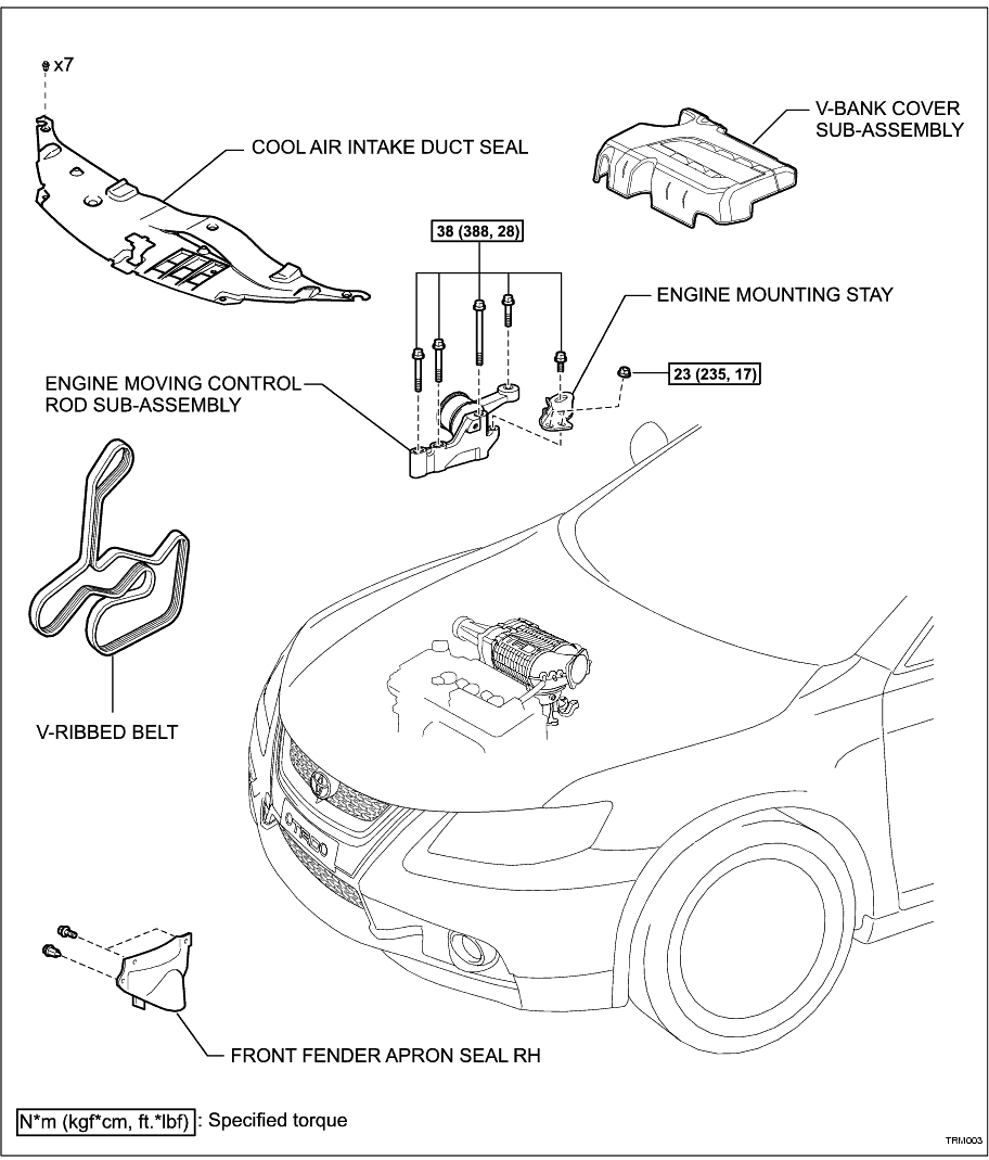
REMOVAL
1. REMOVE FRONT WHEEL RH
2. REMOVE FRONT FENDER APRON SEAL RH
3. REMOVE COOL AIR INTAKE DUCT SEAL (
Click Here
)
4. REMOVE V-BANK COVER SUB-ASSEMBLY (
Click Here
)
5. REMOVE ENGINE MOUNTING STAY
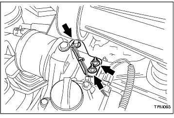
(a) Remove the ground wire cable tie.
-
(b) Remove the bolt, 2 nuts, and the engine mounting stay.
-
6. REMOVE ENGINE MOVING CONTROL ROD SUB-ASSEMBLY
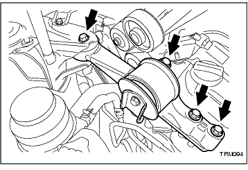
(a) Remove the 4 bolts and engine moving control rod sub-assembly.
-
7. REMOVE V-RIBBED BELT
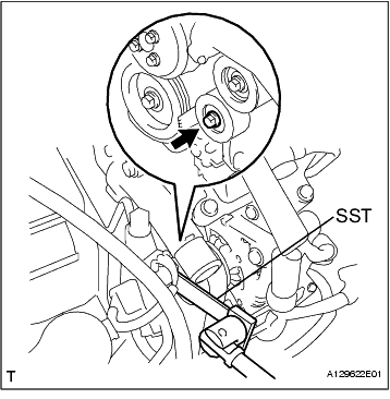
(a) Using SST, release the belt tension by turning the belt tensioner counterclockwise.
SST
09249-63010
-
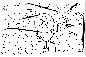
(b) While turning the belt tensioner counterclockwise, align with its holes, and insert a 5 mm bi-hexagon wrench into the holes to fix the V-ribbed belt tensioner.
-
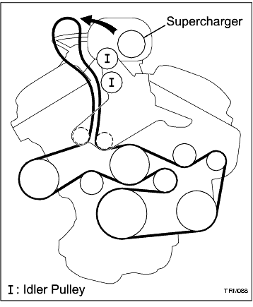
(c) Remove the V-ribbed belt from the supercharger pulley and upper idler bracket assembly pulleys.
-
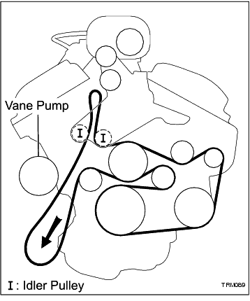
(d) Pull the V-ribbed belt down and remove from the vane pump pulley and lower idler bracket pulleys.
-
(e) Remove the V-ribbed belt from the remaining pulleys.
-
INSPECTION
1. INSPECT V-RIBBED BELT
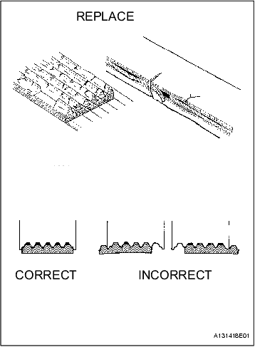
(a) Visually check the V-ribbed belt for excessive wear, frayed cords, etc.
If any defect is found, replace the V-ribbed belt.
HINT:
Cracks on the rib side of a V-ribbed belt are considered acceptable.
If the drive belt has chunks missing from its ribs, it should be replaced.
HINT:
• A new belt is a belt which has been used for less than 5 minutes with the engine running.
• A used belt is a belt which has been used for 5 minutes or more with the engine running.
-
2. INSPECT V-RIBBED BELT TENSIONER ASSEMBLY
(a) Check that nothing is caught in the tensioner by turning it clockwise and counterclockwise.
If a malfunction exists, replace the tensioner.
-
INSTALLATION
1. INSTALL V-RIBBED BELT
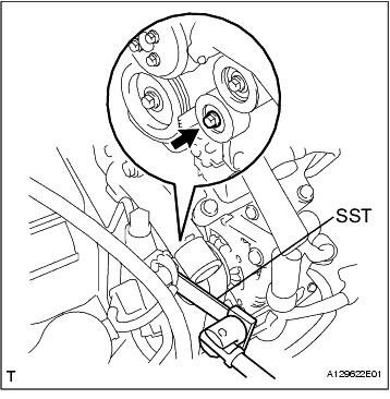
(a) Using SST, lock the belt tensioner pulley by turning the belt tensioner counterclockwise.
SST
09249-63010
-
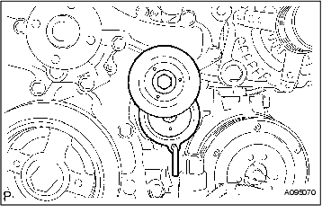
(b) While turning the belt tensioner counterclockwise, align with its holes, and insert a 5 mm bi-hexagon wrench into the holes to fix the V-ribbed belt tensioner.
-
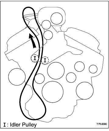
(c) Insert the V-ribbed belt from the bottom, between the lower idler bracket pulleys, leaving a loop near the supercharger pulley.
NOTICE:
Do not attach the belt to the supercharger at this stage.
-
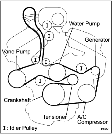
(d) Route the V-ribbed belt in the following order.
1. Water pump pulley.
2. Idler pulley.
3. Generator pulley.
4. A/C compressor pulley.
5. Crankshaft pulley.
6. Tensioner pulley.
7. Below water pump pulley.
8. Idler pulley.
9. Vane pump pulley.
-
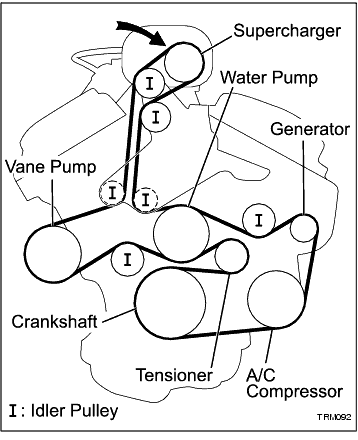
(e) From the top, pull through any remaining slack and route the V-ribbed belt around the upper idler bracket pulleys and supercharger pulley.
-
(f) Confirm the belt is correctly fitted in the grooves of the pulleys.
-
(g) Using SST, turn and hold the belt tensioner counter clockwise and remove the hexagon wrench. Slowly release the tensioner.
SST
09249-63010
-
(h) Check the V-ribbed belt is fitted correctly in the ribbed grooves. Confirm the belt has not slipped out of the grooves on the bottom of the crankshaft pulley by hand.
-
2. INSTALL ENGINE MOVING CONTROL ROD SUB-ASSEMBLY
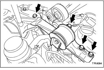
(a) Temporarily install the engine moving control rod sub-assembly with the 4 bolts.
-
(b) Tighten the 4 bolts.
Torque:
38 N*m
(388 kgf*cm,
28 ft.*lbf)
-
3. INSTALL ENGINE MOUNTING STAY
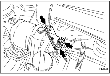
(a) Temporarily install the engine mounting stay with the bolt and 2 nuts.
-
(b) Tighten the bolt and 2 nuts.
Torque:
Bolt
38 N*m
(388 kgf*cm,
28 ft.*lbf)
Nut
23 N*m
(235 kgf*cm,
17 ft.*lbf)
-
(c) Attach the ground wire with a cable tie.
-
4. INSTALL V-BANK COVER SUB-ASSEMBLY (
Click Here
)
5. INSTALL COOL AIR INTAKE DUCT SEAL (
Click Here
)
6. INSTALL FRONT FENDER APRON SEAL RH
7. INSTALL FRONT WHEEL RH