Lumbar Support Adjuster Assembly
Seat
COMPONENTS
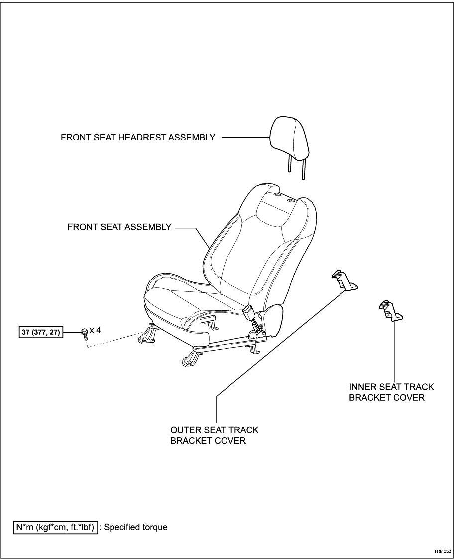
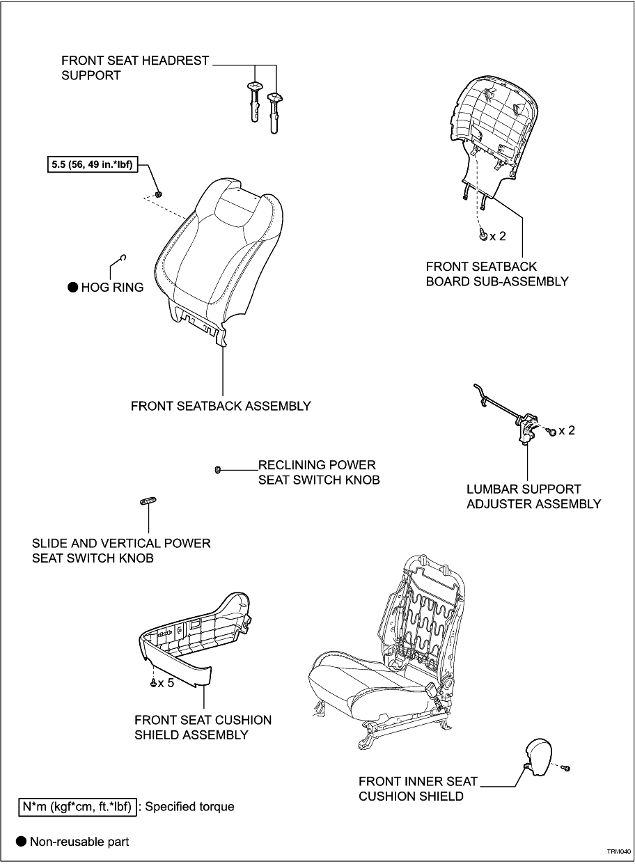
REMOVAL
1. REMOVE FRONT SEAT HEADREST ASSEMBLY
2. REMOVE OUTER SEAT TRACK BRACKET COVER (
Click Here
)
3. REMOVE INNER SEAT TRACK BRACKET COVER (
Click Here
)
4. REMOVE FRONT SEAT ASSEMBLY (
Click Here
)
5. REMOVE RECLINING POWER SEAT SWITCH KNOB (
Click Here
)
6. REMOVE SLIDE AND VERTICAL POWER SEAT SWITCH KNOB (
Click Here
)
7. REMOVE FRONT SEAT CUSHION SHIELD ASSEMBLY (
Click Here
)
8. REMOVE FRONT INNER SEAT CUSHION SHIELD (
Click Here
)
9. REMOVE FRONT SEATBACK BOARD SUB-ASSEMBLY (
Click Here
)
10. REMOVE FRONT SEAT HEADREST SUPPORT (
Click Here
)
11. REMOVE FRONT SEATBACK ASSEMBLY
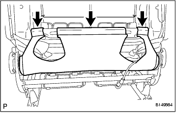
(a) Disengage the 3 hooks.
-
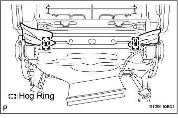
(b) Remove the 2 hog rings.
-
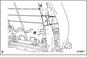
(c) Remove the nut and separate the 2 brackets.
-
(d) Remove the front seatback assembly.
-
12. REMOVE LUMBAR SUPPORT ADJUSTER ASSEMBLY
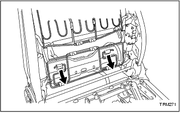
(a) Unattach the seat back spring lower mounts from the frame.
-
(b) Unhook the top of the spring and remove.
-
(c) Disconnect the connector.
-
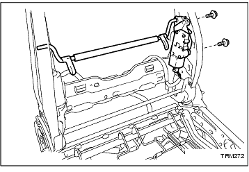
(d) Remove the 2 screws and lumbar support adjuster assembly.
-
INSPECTION
1. INSPECT LUMBAR SUPPORT ADJUSTER ASSEMBLY LH
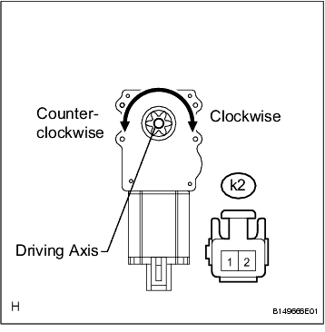
(a) Check operation of the lumbar support adjuster.
-
2. INSPECT LUMBAR SUPPORT ADJUSTER ASSEMBLY RH
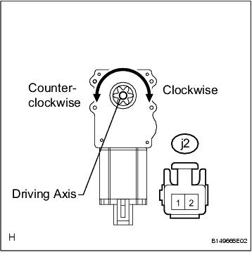
INSTALLATION
1. INSTALL LUMBAR SUPPORT ADJUSTER ASSEMBLY
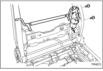
(a) Install the lumbar support adjuster assembly with the 2 screws.
-
(b) Connect the connector.
-
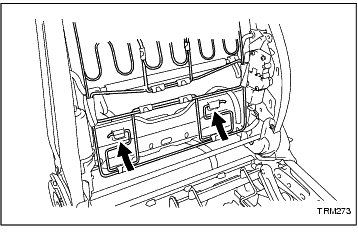
(c) Attach the top of the seat back spring to the frame.
-
(d) Attach the seat back spring lower mounts to the frame.
-
2. INSTALL FRONT SEATBACK ASSEMBLY
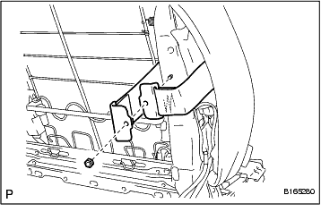
(a) Fully cover the airbag with the 2 seatback cover brackets and tighten the nut.
Torque:
5.5 N*m
(56 kgf*cm,
49 in.*lbf)
NOTICE:
• The seatback cover must be securely installed. Otherwise, the side airbags may not deploy properly.
• Ensure the strap is not twisted after installing the bracket.
• Install the bracket securely.
-
(b) Engage the 3 hooks.
-
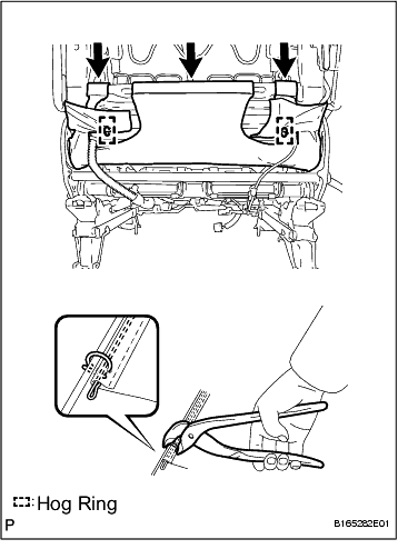
(c) Using hog ring pliers, install 2 new hog rings.
NOTICE:
• Be careful not to damage the cover.
• When installing the hog rings, take care to minimise wrinkles as much as possible.
-
3. INSTALL FRONT SEAT HEADREST SUPPORT (
Click Here
)
4. INSTALL FRONT SEATBACK BOARD SUB-ASSEMBLY (
Click Here
)
5. INSTALL FRONT INNER SEAT CUSHION SHIELD (
Click Here
)
6. INSTALL FRONT SEAT CUSHION SHIELD ASSEMBLY (
Click Here
)
7. INSTALL SLIDE AND VERTICAL POWER SEAT SWITCH KNOB (
Click Here
)
8. INSTALL RECLINING POWER SEAT SWITCH KNOB (
Click Here
)
9. INSTALL FRONT SEAT ASSEMBLY (
Click Here
)
10. INSTALL OUTER SEAT TRACK BRACKET COVER (
Click Here
)
11. INSTALL INNER SEAT TRACK BRACKET COVER (
Click Here
)
12. INSTALL FRONT SEAT HEADREST ASSEMBLY
13. INSPECT SRS WARNING LIGHT
14. INSPECT FRONT SEAT ASSEMBLY