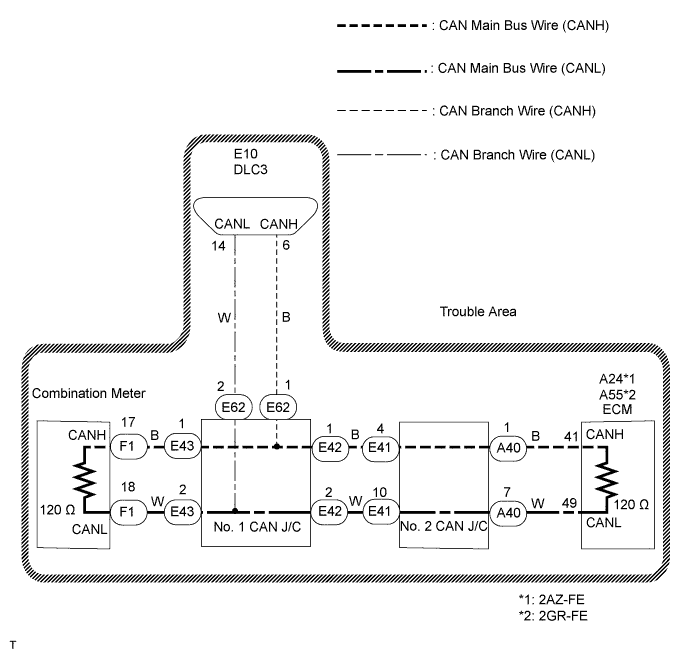
CAN COMMUNICATION SYSTEM (for LHD) > Open in CAN Main Bus Line |
| Symptom | Trouble Area |
| Resistance between terminals 6 (CANH) and 14 (CANL) of the DLC3 is 70 Ω or more. |
|
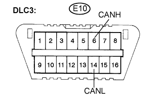
| 1.CHECK DLC3 |
 |
Turn the ignition switch off.
Measure the resistance according to the value(s) in the table below.
| Tester Connection | Condition | Specified Value | Result |
| E10-6 (CANH) -E10-14 (CANL) | Ignition switch off | 108 to 132 Ω | A |
| E10-6 (CANH) - E10-14 (CANL) | Ignition switch off | 133 Ω or higher | B |
|
| ||||
| A | |
 |
| 2.CHECK FOR OPEN IN CAN BUS MAIN WIRE (COMBINATION METER MAIN BUS WIRE) |
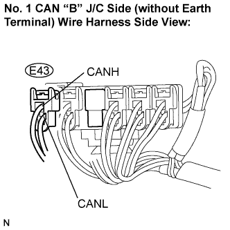 |
Disconnect the CAN main bus wire connector (E43) from the No. 1 CAN J/C B side (without earth terminal).
Measure the resistance according to the value(s) in the table below.
| Tester Connection | Condition | Specified Value |
| E43-1 (CANH) - E43-2 (CANL) | Ignition switch off | 108 to 132 Ω |
|
| ||||
| OK | |
|
| 3.CHECK FOR OPEN IN CAN BUS MAIN WIRE (NO. 1 CAN J/C) |
 |
Reconnect the CAN main bus wire connector (E43) to the No. 1 CAN J/C B side (without earth terminal).
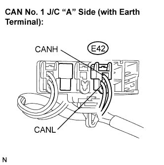
Disconnect the CAN main bus wire connector (E42) from the No. 1 CAN J/C A side (with earth terminal).
Measure the resistance according to the value(s) in the table below.
| Tester Connection | Condition | Specified Value |
| E41-1 (CANH) - E41-2 (CANL) | Ignition switch off | 108 to 132 Ω |
|
| ||||
| NG | |
|
| 4.CHECK FOR OPEN IN CAN BUS MAIN WIRE (NO. 1 CAN J/C - NO. 2 CAN J/C) |
Reconnect the CAN main bus wire connector (E42) to the No. 1 CAN J/C A side (with earth terminal).
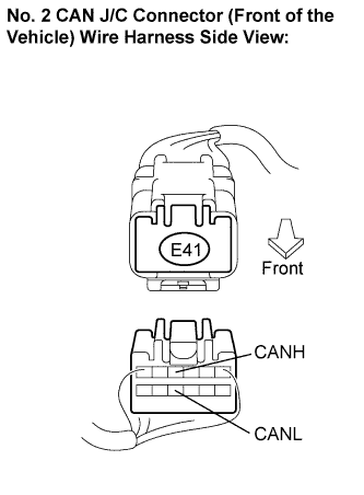 |
Disconnect the CAN main bus wire connector (E41) from the No. 2 CAN J/C (front of the vehicle).
Measure the resistance according to the value(s) in the table below.
| Tester Connection | Condition | Specified Value |
| E41-4 (CANH) - E41-10 (CANL) | Ignition switch off | 108 to 132 Ω |
|
| ||||
| OK | |
|
| 5.CHECK FOR OPEN IN CAN BUS MAIN WIRE (NO. 2 CAN J/C) |
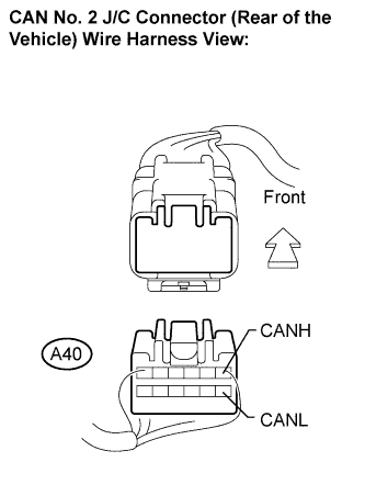 |
Reconnect the CAN main bus wire connector (E41) to the No. 2 CAN J/C (front of the vehicle).
Disconnect the CAN main bus wire connector (A40) from the No. 2 CAN J/C (rear of the vehicle).
Measure the resistance according to the value(s) in the table below.
| Tester Connection | Condition | Specified Value |
| A40-1 (CANH) - A40-7 (CANL) | Ignition switch off | 108 to 132 Ω |
|
| ||||
| NG | |
|
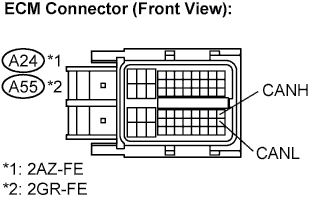
| 6.CHECK FOR OPEN IN CAN BUS MAIN WIRE (ECM CAN MAIN BUS WIRE) |
 |
Reconnect the CAN main bus wire connector (A40) to the No. 2 CAN J/C (rear of the vehicle).
Disconnect the ECM connector.
Measure the resistance according to the value(s) in the table below.
| Tester Connection | Condition | Specified Value |
| A24-41 (CANH) - A24-49 (CANL) | Ignition switch off | 108 to 132 Ω |
| Tester Connection | Condition | Specified Value |
| A55-41 (CANH) - A55-49 (CANL) | Ignition switch off | 108 to 132 Ω |
|
| ||||
| NG | ||
 | ||
| ||
| 7.CHECK FOR OPEN IN CAN BUS MAIN WIRE (COMBINATION METER - NO. 1 CAN J/C) |
Reconnect the CAN main bus wire connector (E43) to the No. 1 CAN J/C B side (without earth terminal).
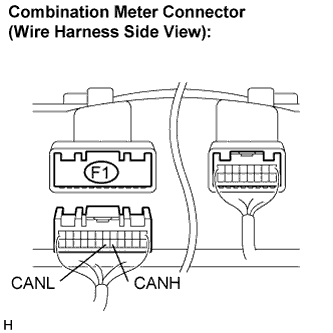 |
Disconnect the combination meter connector (F1).
Measure the resistance according to the value(s) in the table below.
| Tester Connection | Condition | Specified Value |
| F1-17 (CANH) - F1-18 (CANL) | Ignition switch off | 108 to 132 Ω |
|
| ||||
| NG | ||
| ||
| ||

