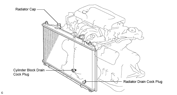
Loosen the radiator drain cock plug and cylinder block drain cock plug, then drain the coolant.
- HINT:
- Collect the coolant in a container and dispose of it according to the regulations in your area.
AUTOMATIC TRANSAXLE ASSEMBLY > REMOVAL |
| 1. DISCHARGE FUEL SYSTEM PRESSURE |
| 2. DISCONNECT CABLE FROM NEGATIVE BATTERY TERMINAL |
| 3. PLACE FRONT WHEELS FACING STRAIGHT AHEAD |
| 4. REMOVE FRONT WHEELS |
| 5. REMOVE ENGINE UNDER COVER LH |
| 6. REMOVE ENGINE UNDER COVER RH |
| 7. REMOVE FRONT FENDER APRON SEAL RH |
| 8. DRAIN ENGINE OIL |
Remove the oil filler cap.
Remove the oil drain plug and drain the oil into a container.
| 9. DRAIN ENGINE COOLANT |
Remove the radiator cap sub-assembly from the radiator assembly.
Loosen the radiator drain cock plug and cylinder block drain cock plug, then drain the coolant.
| 10. DRAIN AUTOMATIC TRANSAXLE FLUID |
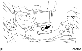
Using a 6 mm socket hexagon wrench, remove the drain plug and gasket, and drain ATF.
Install a new gasket and the drain plug.
| 11. REMOVE WINDSHIELD WIPER LINK ASSEMBLY |
| 12. REMOVE COWL TOP PANEL OUTER SUB-ASSEMBLY |
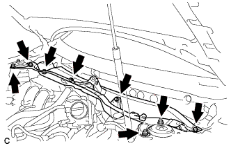 |
Remove the 4 bolts, 4 nuts and outer cowl top panel sub-assembly.
| 13. REMOVE NO. 1 ENGINE COVER SUB-ASSEMBLY |
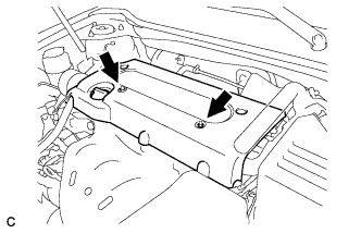 |
Remove the 2 nuts and cover.
| 14. REMOVE V-RIBBED BELT |
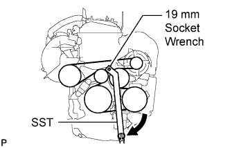 |
Using SST and 19 mm socket wrench, loosen the V-ribbed belt tensioner arm clockwise, then remove the V-ribbed belt.
| 15. REMOVE AIR CLEANER INLET ASSEMBLY |
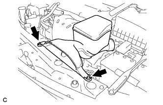 |
Remove the 2 bolts, clamp and air cleaner inlet.
| 16. REMOVE AIR CLEANER CAP SUB-ASSEMBLY |
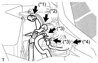 |
Disconnect the mass air flow meter connector (*1).
Disconnect the purge VSV connector (*2).
Disconnect the 2 purge VSV vacuum hoses (*3).
Disconnect the purge line hose from the clamp (*4).
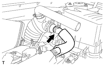 |
Disconnect the No. 2 ventilation hose from the air cleaner hose.
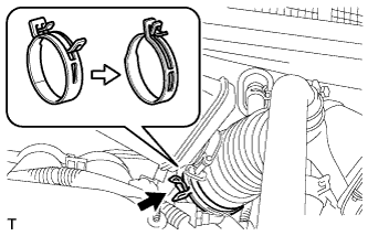 |
Lock the No. 1 air cleaner hose clamp, and then disconnect the No. 1 air cleaner hose from the throttle body.
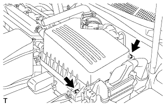 |
Remove the 2 bolts and air cleaner cap.
Remove the air cleaner filter element from the air cleaner case.
| 17. REMOVE AIR CLEANER CASE SUB-ASSEMBLY |
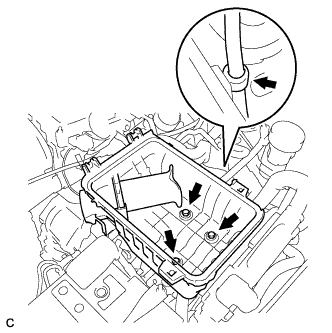 |
Disconnect the hose clamp.
Remove the 3 bolts and air cleaner case.
| 18. REMOVE BATTERY |
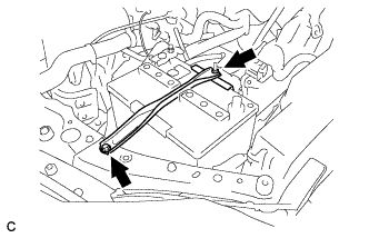 |
Loosen the bolt and nut, and remove the battery clamp.
Remove the battery and battery tray.
| 19. REMOVE NO. 2 ENGINE MOUNTING STAY RH |
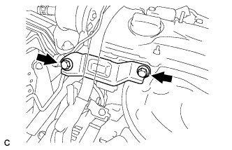 |
Remove the 2 bolts and No. 2 mounting stay RH.
| 20. REMOVE ENGINE MOVING CONTROL ROD SUB-ASSEMBLY |
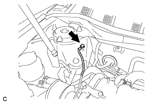 |
Remove the bolt and disconnect the ground cable.
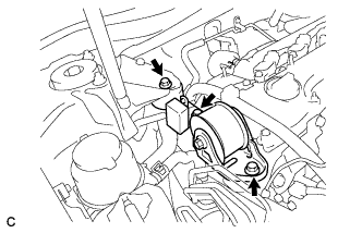 |
Remove the 3 bolts and the engine moving control rod with bracket.
| 21. REMOVE NO. 2 ENGINE MOUNTING BRACKET RH |
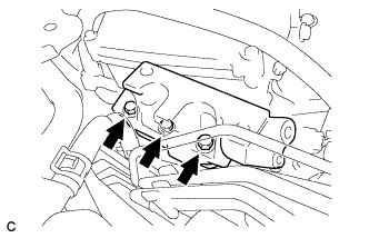 |
Remove the 3 bolts and No. 2 mounting bracket RH.
| 22. DISCONNECT NO. 1 VACUUM HOSE CONNECTOR |
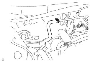 |
Remove the clamp and disconnect the vacuum hose connector.
| 23. DISCONNECT RADIATOR HOSE INLET |
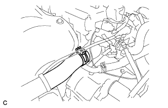 |
Remove the clamp and disconnect the radiator hose inlet.
| 24. DISCONNECT RADIATOR HOSE OUTLET |
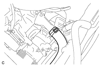 |
Remove the clamp and disconnect the radiator hose outlet.
| 25. DISCONNECT OIL COOLER INLET HOSE |
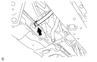 |
Disconnect the oil cooler inlet hose from the radiator assembly.
| 26. DISCONNECT OIL COOLER OUTLET HOSE |
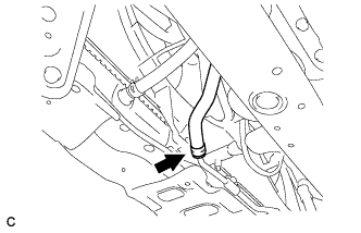 |
Disconnect the oil cooler outlet hose from the radiator assembly.
| 27. DISCONNECT HEATER WATER HOSE INLET |
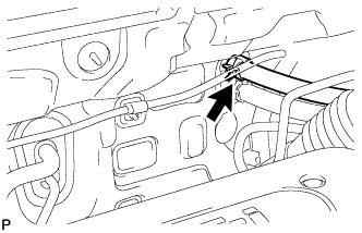 |
Disconnect the heater inlet water hose.
| 28. DISCONNECT HEATER WATER HOSE OUTLET |
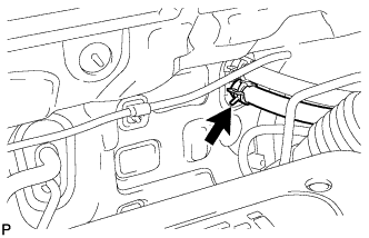 |
Disconnect the heater outlet water hose.
| 29. REMOVE ECM |
| 30. DISCONNECT ENGINE WIRE |
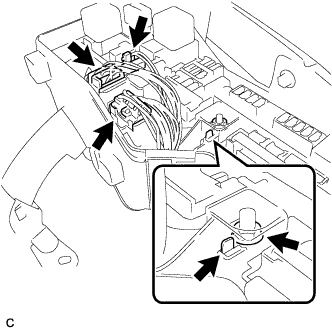 |
Disconnect the engine wire from the engine room relay block.
Remove the nut and separate the wire harness.
Using a screwdriver, unlock the engine room R/B. Pull the engine room R/B upward.
Disconnect the engine wire connectors.
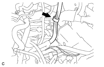 |
Remove the clamp from the bracket.
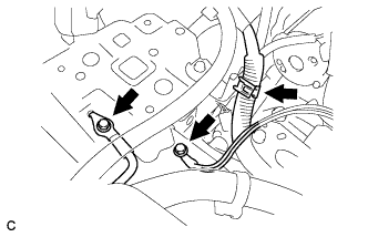 |
Remove the 2 bolts and clamp from the body.
| 31. DISCONNECT TRANSMISSION CONTROL CABLE ASSEMBLY |
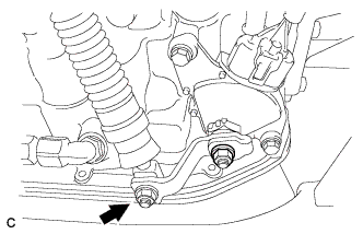 |
Remove the nut from the control shaft lever.
Disconnect the transmission control cable assembly from the control shaft lever.
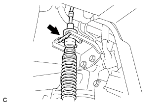 |
Remove the clip and disconnect the transmission control cable assembly from the No. 1 control cable bracket.
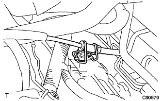 |
Disconnect the transmission control cable assembly from the control cable clamp.
| 32. DISCONNECT NO. 1 OIL RESERVOIR TO PUMP HOSE |
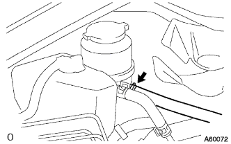 |
Disconnect the No. 1 oil reservoir to pump hose.
| 33. DISCONNECT RETURN TUBE SUB-ASSEMBLY |
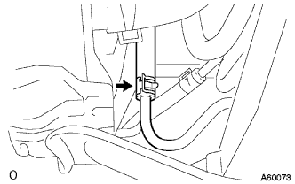 |
Disconnect the return tube sub-assembly.
| 34. DISCONNECT FUEL TUBE SUB-ASSEMBLY |
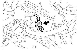 |
Remove the No. 1 fuel pipe clamp.
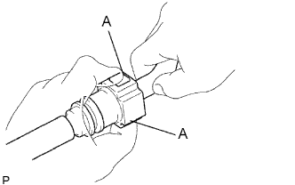 |
Disconnect the connector from the tube while pinching part A with your fingers as shown in the illustration.
| 35. REMOVE GENERATOR ASSEMBLY |
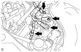 |
Disconnect the generator connector.
Remove the nut and disconnect the wire harness from terminal B.
Remove the bolt and wire harness clamp bracket.
Remove the wire harness clamps.
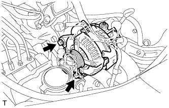 |
Remove the 2 bolts and generator assembly.
| 36. SEPARATE COMPRESSOR AND MAGNETIC CLUTCH |
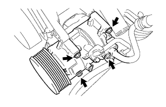 |
Disconnect the connector.
Remove the 4 bolts and separate the compressor.
| 37. REMOVE FRONT EXHAUST PIPE ASSEMBLY |
Remove the 2 nuts.
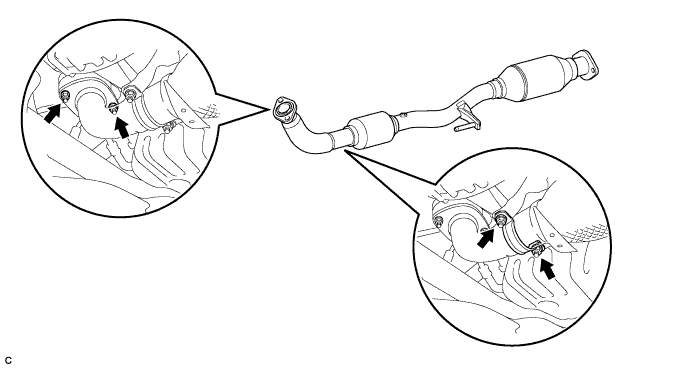
Remove the 2 nuts, front exhaust pipe No. 1 support bracket and front exhaust pipe assembly.
Remove the gasket from the exhaust manifold.
| 38. REMOVE FRONT AXLE HUB NUT LH |
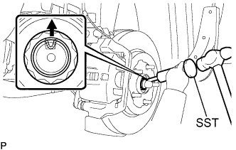 |
Using SST and a hammer, release the staked part of the front axle hub nut.
While applying the brakes, remove the front axle hub nut.
| 39. REMOVE FRONT AXLE HUB NUT RH |
| 40. REMOVE FRONT STABILIZER LINK ASSEMBLY LH |
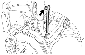 |
Remove the nut and separate the front stabilizer link assembly.
| 41. REMOVE FRONT STABILIZER LINK ASSEMBLY RH |
| 42. REMOVE FRONT SPEED SENSOR LH |
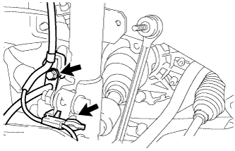 |
Remove the bolt and clip, and separate the speed sensor wire and flexible hose from the shock absorber.
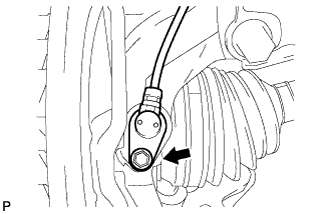 |
Remove the bolt and separate the speed sensor from the steering knuckle.
| 43. REMOVE FRONT SPEED SENSOR RH |
| 44. DISCONNECT TIE ROD ASSEMBLY LH |
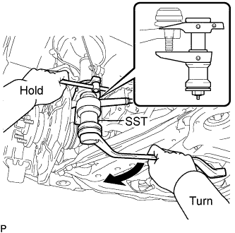 |
Remove the cotter pin and nut.
Using SST, separate the tie rod end sub-assembly from the steering knuckle.
| 45. DISCONNECT TIE ROD ASSEMBLY RH |
| 46. DISCONNECT FRONT SUSPENSION LOWER NO. 1 ARM LH |
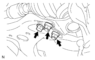 |
Remove the bolt and 2 nuts, and separate the front suspension lower No. 1 arm from the lower ball joint.
| 47. DISCONNECT FRONT SUSPENSION LOWER NO. 1 ARM RH |
| 48. SEPARATE FRONT AXLE ASSEMBLY LH |
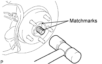 |
Put matchmarks on the front drive shaft assembly and the axle hub.
Using a plastic hammer, separate the front drive shaft assembly from the front axle assembly.
| 49. SEPARATE FRONT AXLE ASSEMBLY RH |
| 50. REMOVE DRIVE PLATE AND TORQUE CONVERTER CLUTCH SETTING BOLT |
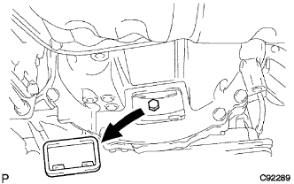 |
Remove the flywheel housing under cover.
 |
Turn the crankshaft to gain access and remove the 6 bolts while holding the crankshaft pulley bolt with a wrench.
| 51. SEPARATE STEERING SLIDING YOKE |
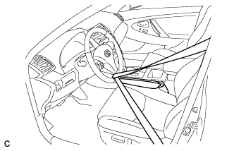 |
Secure the steering wheel with the seat belt in order to prevent rotation.
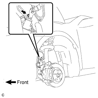 |
Remove the bolt and slide the steering sliding yoke.
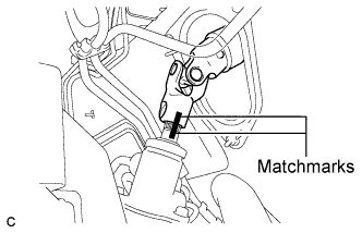 |
Put matchmarks on the steering sliding yoke and the power steering link assembly.
Separate the steering sliding yoke from the power steering link assembly.
| 52. REMOVE ENGINE ASSEMBLY WITH TRANSAXLE |
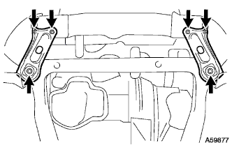 |
Set the engine lifter.
Remove the 4 bolts, 2 nuts and frame side rail plate RH and LH.
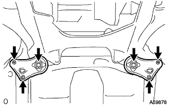 |
Remove the 4 bolts, 2 nuts and front suspension member brace rear RH and LH.
Carefully remove the engine assembly from the vehicle.
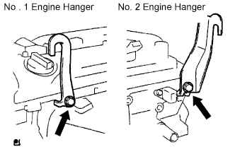 |
Install the 2 engine hangers as shown in the illustration.
Parts No.:
| Parts | Parts No. |
| No. 1 Engine hanger | 12281-28010 |
| No. 2 Engine hanger | 12282-28010 |
| Bolt | 91512-61020 |
Using a chain block and an engine sling device, hang the engine assembly.
| 53. REMOVE VANE PUMP ASSEMBLY |
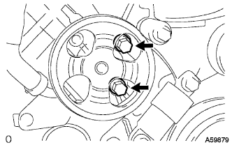 |
Disconnect the oil pressure switch connector.
Loosen the 2 bolts and remove the vane pump from the engine.
| 54. REMOVE FRONT FRAME ASSEMBLY |
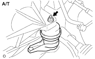 |
A/T:
Remove the nut from the engine mounting insulator LH.
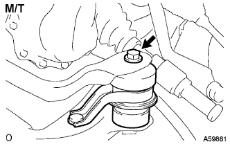 |
M/T:
Remove the bolt from the engine mounting insulator LH.
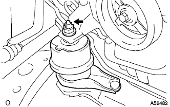 |
Remove the nut from the engine mounting insulator RH.
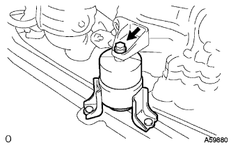 |
Remove the bolt from the engine mounting insulator FR.
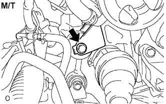 |
M/T:
Remove the bolt from the engine lateral control rod.
Raise the engine assembly and separate the front frame.
| 55. REMOVE FRONT DRIVE SHAFT ASSEMBLY LH |
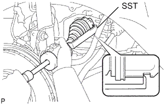 |
Using SST, remove the front drive shaft assembly LH.
| 56. REMOVE FRONT DRIVE SHAFT ASSEMBLY RH |
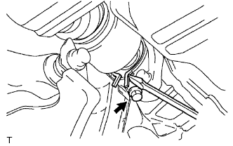 |
Using a screwdriver, remove the bearing bracket hole snap ring.
Remove the bolt and front drive shaft assembly RH from the drive shaft bearing bracket.
| 57. REMOVE ENGINE WIRE |
| 58. REMOVE STARTER ASSEMBLY |
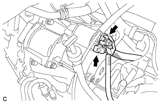 |
Disconnect the terminal 50 connector from the starter assembly.
Remove the nut and disconnect the wire harness from terminal 30.
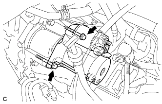 |
Remove the 2 bolts and starter assembly.
| 59. REMOVE ENGINE MOUNTING FRONT BRACKET |
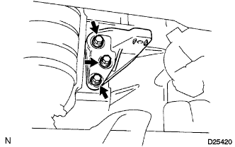 |
Remove the 3 bolts and engine mounting front bracket.
| 60. SEPARATE AUTOMATIC TRANSAXLE ASSEMBLY |
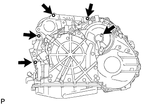 |
Remove the 5 bolts.
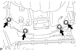 |
Remove the 4 lower side mounting bolts.
Separate and remove the automatic transaxle.
| 61. REMOVE TORQUE CONVERTER CLUTCH ASSEMBLY |
| 62. REMOVE SPEEDOMETER DRIVEN HOLE COVER SUB-ASSEMBLY |
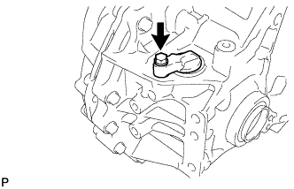 |
Remove the bolt and hole cover from the transaxle case.
Remove the O-ring from the hole cover.
| 63. REMOVE NO. 2 TRANSMISSION CONTROL CABLE BRACKET |
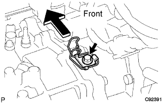 |
Remove the bolt and No. 2 transmission control cable bracket.
| 64. REMOVE WIRE HARNESS CLAMP BRACKET |
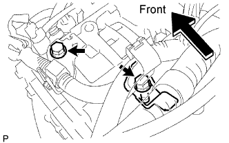 |
Disconnect the wire harnesses from the 2 brackets.
Remove the 2 bolts and 2 clamps.
| 65. DISCONNECT WIRE HARNESS |
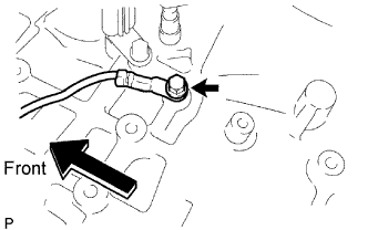 |
Remove the bolt and disconnect the wire harness.
| 66. DISCONNECT CONNECTORS |
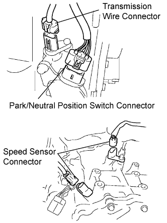 |
Disconnect the transmission wire connector.
Disconnect the park/neutral position switch connector.
Disconnect the 2 speed sensor connectors.
| 67. REMOVE NO. 1 TRANSMISSION CONTROL CABLE BRACKET |
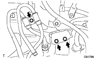 |
Remove the bolt and oil cooler tube clamp.
Remove the 2 bolts and No. 1 transmission control cable bracket.
| 68. REMOVE TRANSMISSION OIL FILLER TUBE SUB-ASSEMBLY |
Remove the ATF level gauge.
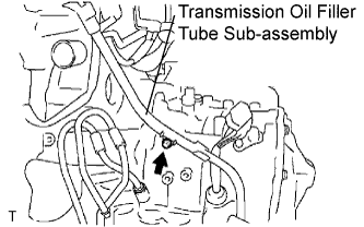 |
Remove the bolt and transmission oil filler tube sub-assembly.
Remove the O-ring from the oil filler tube sub-assembly.
| 69. REMOVE NO. 1 OIL COOLER INLET TUBE |
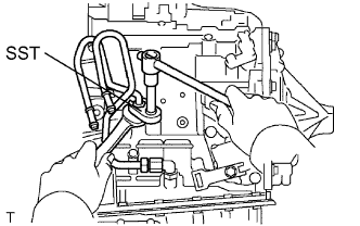 |
Using SST and a wrench, disconnect the No. 1 oil cooler inlet tube.
| 70. REMOVE NO. 1 OIL COOLER OUTLET TUBE |
Using SST and a wrench, disconnect the No. 1 oil cooler outlet tube.
| 71. REMOVE TRANSAXLE CASE UPPER COVER |
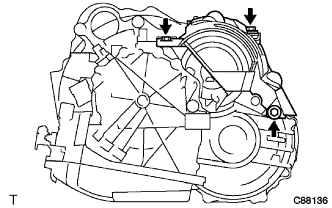 |
Remove the 3 bolts and transaxle case upper cover.