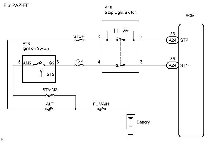
DTC P0571 Brake Switch "A" Circuit |
| DTC No. | DTC Detection Condition | Trouble Area |
| P0571 | When voltage of STP terminal and that of ST1- terminal of ECM are less than 1 V for 0.5 sec. or more |
|
| 1.READ VALUE ON INTELLIGENT TESTER |
Connect the intelligent tester to the DLC3.
Turn the ignition switch to ON, and turn the intelligent tester main switch on.
Check the DATA LIST for proper functioning of the stop light switch.
| Item | Measurement Item / Display (Range) | Normal Condition | Diagnostic Note |
| Stop Light SW M-CPU | Stop light switch signal (Main CPU) / ON or OFF | ON: Brake pedal depressed OFF: Brake pedal released | - |
| Result | Proceed to |
| NG | A |
| OK (for 2AZ-FE) | B |
| OK (for 2GR-FE) | C |
|
| ||||
|
| ||||
| A | |
 |
| 2.CHECK HARNESS AND CONNECTOR (STOP LIGHT SWITCH - BATTERY) |
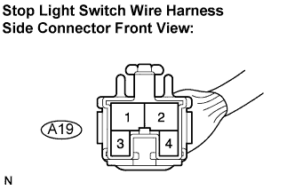 |
Disconnect the stop light switch connector.
Measure the voltage according to the value(s) in the table below.
| Tester Connection | Condition | Specified Condition |
| A19-2 - Body ground | Always | 10 to 14 V |
| A19-4 - Body ground | Ignition switch on (IG) | 10 to 14 V |
|
| ||||
| OK | |
|
| 3.INSPECT STOP LIGHT SWITCH |
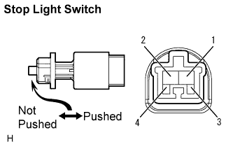 |
Remove the stop light switch (Click here).
Measure the resistance according to the value(s) in the table below.
| Tester Connection | Switch Condition | Specified Condition |
| 1 - 2 | Switch pin not pushed | Below 1 Ω |
| 3 - 4 | Switch pin not pushed | 10 kΩ or higher |
| 1 - 2 | Switch pin pushed | 10 kΩ or higher |
| 3 - 4 | Switch pin pushed | Below 1 Ω |
Install the stop light switch (Click here).
|
| ||||
| OK | |
|
| 4.CHECK ECM |
Reconnect the stop light switch connector.
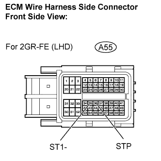 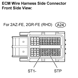 |
Disconnect the ECM connector.
Turn the ignition switch to ON.
Measure the voltage according to the value(s) in the table below.
| Tester Connection | Brake Pedal Condition | Specified Condition |
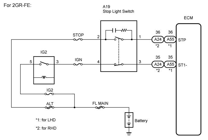
| A55-36 (STP) - Body ground | Depressed | 10 to 14 V |
| A55-36 (STP) - Body ground | Released | Below 1 V |
| A55-35 (ST1-) - Body ground | Depressed | Below 1 V |
| A55-35 (ST1-) - Body ground | Released | 10 to 14 V |
| Tester Connection | Brake Pedal Condition | Specified Condition |
| A24-36 (STP) - Body ground | Depressed | 10 to 14 V |
| A24-36 (STP) - Body ground | Released | Below 1 V |
| A24-35 (ST1-) - Body ground | Depressed | Below 1 V |
| A24-35 (ST1-) - Body ground | Released | 10 to 14 V |
| Result | Proceed to |
| NG | A |
| OK (for 2AZ-FE) | B |
| OK (for 2GR-FE) | C |
|
| ||||
|
| ||||
| A | ||
 | ||
| ||
