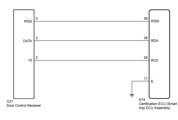
DTC B1242 Wireless Door Lock Tuner Circuit Malfunction |
| DTC No. | DTC Detection Condition | Trouble Area |
| B1242 | The certification ECU (smart key ECU assembly) detects that there is a short in the circuit between terminals RSSI, or between terminals DATA and RDA. |
|
| 1.CHECK HARNESS AND CONNECTOR (CERTIFICATION ECU - DOOR CONTROL RECEIVER) |
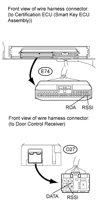 |
Disconnect the E74 certification ECU (smart key ECU assembly) connector and O27 door control receiver connector.
Measure the resistance according to the value(s) in the table below.
| Tester Connection | Condition | Specified Condition |
| E74-39 (RSSI) - O27-5 (RSSI) | Always | Below 1 Ω |
| E74-38 (RDA) - O27-3 (DATA) | Always | Below 1 Ω |
| E74-39 (RSSI) - E74-38 (RDA) | Always | 10 kΩ or higher |
| E74-39 (RSSI) - Body ground | Always | 10 kΩ or higher |
| E74-38 (RDA) - Body ground | Always | 10 kΩ or higher |
|
| ||||
| OK | |
 |
| 2.INSPECT CERTIFICATION ECU (SMART KEY ECU ASSEMBLY) |
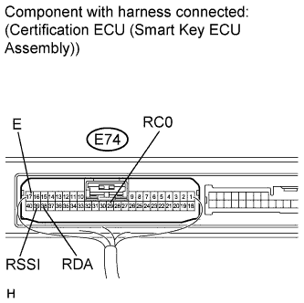 |
Reconnect the E74 ECU connector.
Measure the voltage and check for pulse according to the value(s) in the table below.
| Tester Connection | Condition | Specified Condition |
| E74-29 (RC0) - E74-17 (E) | Engine switch off, all doors closed and transmitter switch not pressed | Pulse generation |
| Engine switch off, all doors closed and transmitter switch pressed | 4.6 to 5.4 V |
|
| ||||
| OK | ||
 | ||
| ||
