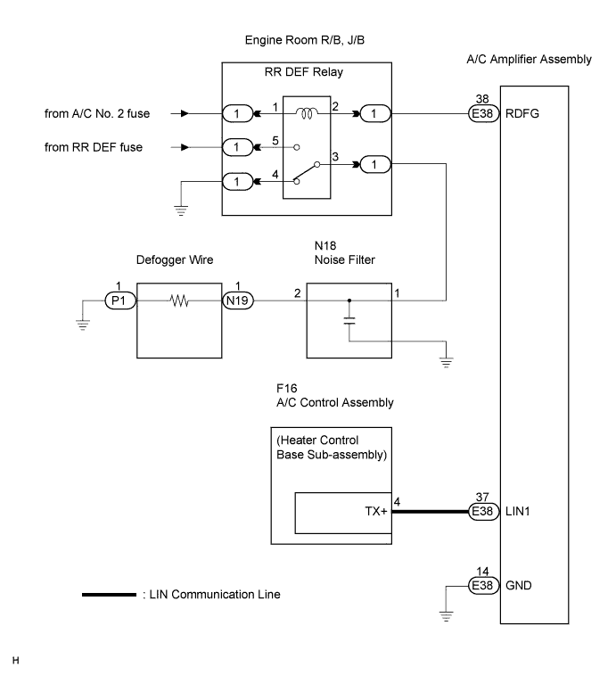
WINDOW DEFOGGER SYSTEM > Rear Window Defogger System does not Operate |
| 1.PERFORM ACTIVE TEST USING INTELLIGENT TESTER |
Select the ACTIVE TEST, use the intelligent tester to issue a control command, and then check the window defogger operation.
| Item | Test Details |
| Defogger Relay (Rear) | Turns rear window defogger OFF/ON |
|
| ||||
| OK | |
 |
| 2.CHECK WIRE HARNESS (A/C CONTROL ASSEMBLY - A/C AMPLIFIER ASSEMBLY) |
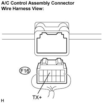 |
Disconnect the connector from the A/C control assembly (heater control base sub-assembly).
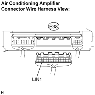 |
Disconnect the connector from the A/C amplifier.
Measure the resistance according to the value(s) in the table below.
| Tester Connection (Symbols) | Condition | Specified Condition |
| E38-37 (LIN1) - F16-4 (TX+) | Always | Below 1 Ω |
| E38-37 (LIN1) - Body ground | Always | 10 kΩ or higher |
|
| ||||
| OK | |
|
| 3.REPLACE HEATER CONTROL BASE SUB-ASSEMBLY |
Replace the heater control base sub-assembly.
| NEXT | |
|
| 4.CONFIRM REAR WINDOW DEFOGGER OPERATION |
Turn the ignition switch ON, press the defogger switch, and check that the window defogger operates.
|
| ||||
| OK | ||
 | ||
| ||
| 5.PERFORM ACTIVE TEST USING INTELLIGENT TESTER |
Select the ACTIVE TEST, use the intelligent tester to issue a control command, and then check the DEFOG relay operation.
Check that operation sound of the RR DEF relay is heard.
| Relay operating sound is heard | OK |
| Relay operating sound is not heard | NG |
|
| ||||
| NG | |
|
| 6.INSPECT RR DEF RELAY |
|
| ||||
| OK | |
|
| 7.CHECK WIRE HARNESS (RR DEF RELAY - BATTERY POSITIVE) |
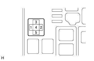 |
Disconnect the RR DEF relay.
Measure the voltage according to the value(s) in the table below.
| Tester Connection | Condition | Specified Condition |
| 1 - Body ground | Ignition switch ON | 10 to 14 V |
|
| ||||
| OK | |
|
| 8.CHECK WIRE HARNESS (RR DEF RELAY - A/C AMPLIFIER ASSEMBLY) |
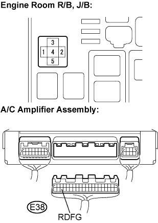 |
Disconnect the RR DEF relay and A/C amplifier assembly connector.
Measure the resistance according to the value(s) in the table below.
| Tester Connection | Condition | Specified Condition |
| 2 - E38-38 | Always | Below 1 Ω |
| 2 - Body ground | Always | 10 kΩ or higher |
|
| ||||
| OK | ||
| ||
| ||
| 9.CHECK WIRE HARNESS (RR DEF RELAY - BATTERY POSITIVE AND BODY GROUND) |
|
Disconnect the RR DEF relay.
Measure the voltage and resistance according to the value(s) in the table below.
| Tester Connection | Condition | Specified Condition |
| 4 - Body ground | Always | Below 1 Ω |
| Tester Connection | Condition | Specified Condition |
| 5 - Body ground | Always | 10 to 14 V |
|
| ||||
| OK | |
|
| 10.INSPECT NOISE FILTER |
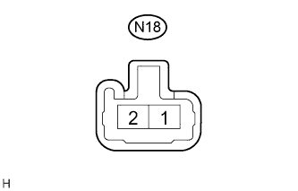 |
Disconnect the noise filter connector.
Measure the resistance according to the value(s) in the table below.
| Tester Connection | Condition | Specified Condition |
| N18-1 - N18-2 | Always | Below 1 Ω |
| N18-1 - Body ground | Always | 10 kΩ or higher |
|
| ||||
| OK | |
|
| 11.CHECK WIRE HARNESS (RR DEF RELAY - NOISE FILTER) |
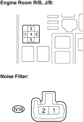 |
Disconnect the RR DEF relay and defogger wire connectors.
Measure the resistance according to the value(s) in the table below.
| Tester Connection | Condition | Specified Condition |
| 3 - N18-2 | Always | Below 1 Ω |
| 3 - Body ground | Always | 10 kΩ or higher |
|
| ||||
| OK | |
|
| 12.CHECK WIRE HARNESS (NOISE FILTER - DEFOGGER WIRE CONNECTOR) |
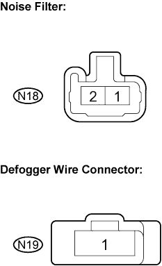 |
Measure the resistance according to the value(s) in the table below.
| Tester Connection | Condition | Specified Condition |
| N18-1 - N19-1 | Always | Below 1 Ω |
| N18-1 - Body ground | Always | 10 kΩ or higher |
|
| ||||
| OK | |
|
| 13.CHECK WIRE HARNESS (DEFOGGER WIRE CONNECTOR - BODY GROUND) |
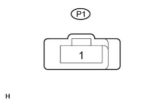 |
Measure the resistance according to the value(s) in the table below.
| Tester Connection | Condition | Specified Condition |
| P1-1 - Body ground | Always | Below 1 Ω |
|
| ||||
| OK | ||
| ||
| ||

